Download

1 / 16
160 likes | 355 Views
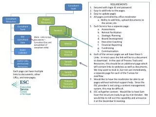
Practice 2. Asst. Prof. Dr. Alper ŞİŞMAN. GPIO Module. Output states: push-pull or open drain + pull-up/down Output data from output data register ( GPIOx_ODR ) or peripheral (alternate function output) Speed selection for each I/O Input states: floating, pull-up/down, analog

E N D
Practice 2 Asst. Prof. Dr. Alper ŞİŞMAN
GPIO Module • Output states: push-pull or open drain + pull-up/down • Output data from output data register (GPIOx_ODR) or peripheral (alternate function output) • Speed selection for each I/O • Input states: floating, pull-up/down, analog • Input data to input data register (GPIOx_IDR) or peripheral (alternate function input) • Bit set and reset register (GPIOx_BSRR) for bitwise write access to GPIOx_ODR
Locking mechanism (GPIOx_LCKR) provided to freeze the I/O configuration • Analog function • Alternate function input/output selection registers (at most 16 AFs per I/O) • Fast toggle capable of changing every two clock cycles • Highly flexible pin multiplexing allows the use of I/O pins as GPIOs or as one of several peripheral functions • During and just after reset, the alternate functions are not active and the I/O ports are configured in input floating mode.
The configuration steps of GPIO pin • The clock signal of corresponding GPIO HW must be activated: • RCC->AHB1ENR: Reset&Clock control reg.->AHB1 enable register. • The pins must be defined as input or output • GPIOD->MODER: Mode register 32-bit for 16 pins:
The output type must be configured • GPIOD=>OTYPER: • The output speed must be configured • GPIOD=>OSPEEDR: 32 bit register for 16 pins.
The pull up resistor configuration mus be set • GPIOD=>PUPDR: 32 bit reg.16 pins
Read/Write Registers • GPIO port input data register: GPIOD=>IDR • GPIO port output data reg.:GPIOD=>ODR • GPIO port bit set/reset reg.: GPIOD=>BSRR
Other GPIO Registers • GPIO port configuration lock reg. • GPIO alternate function low reg. • GPIO alternate function high reg. • Further information can be seen on page 278. (ref manual RM0090)
Blinking LED • Run in DEBUG mode step by step and see four LED in on and off. • #include "STM32F4xx.h” • void SystemInit() • { • (*((int*)0xE000ED88))|=0x0F00000; // Floating Point donaniminiaktiflestir. • RCC->AHB1ENR |= 0x00000008; // GPIOD donaniminin clock sinyaliniuygulayalim • GPIOD->MODER = 0x55000000; // GPIOD nin 15, 14, 13, 12 pinlericikistanimlandi (Ledlerbupinlerde) • GPIOD->OSPEEDR= 0xFFFFFFFF; // GPIOD nin tum cikislari en yuksekhizdakullanacagiz • }
int main() • { • while(1) • { • GPIOD->ODR= 0x0000F000; // Ledleryansin • GPIOD->ODR= 0x00000000; // Ledlersonsun • } • }
Add a delay subrotine • void delayy(){ • int delay0 = 0x000FFFFF; • while (delay0--){ • }
Call delayy from main • int main() • { • while(1) • { • GPIOD->ODR= 0x0000F000; // Ledleryansin • delayy(); • GPIOD->ODR= 0x00000000; // Ledlersonsun • delayy(); • } • }
Read Button • Activate GPIOA clock • Configure A0 as input (it is default), bus speed and no pull up/down • void SystemInit() • { • (*((int*)0xE000ED88))|=0x0F00000; // Floating Point donaniminiaktiflestir. • RCC->AHB1ENR |= 0x00000009; // GPIOD &A donaniminin clock sinyaliniuygulayalim • GPIOD->MODER = 0x55000000; // GPIOD nin 15, 14, 13, 12 pinlericikistanimlandi (Ledlerbupinlerde) • GPIOD->OSPEEDR= 0xFFFFFFFF; // GPIOD nin tum cikislari en yuksekhizdakullanacagiz • GPIOA->OSPEEDR= 0xFFFFFFFF; // GPIOA nin tum girisleri en yuksekhizdakullanacagiz • GPIOA->PUPDR = 0x00000000; }
Stop blinking • When button is pressed the blinking will stop: • int main() • { • while(1) • { • while ((GPIOA->IDR & 0x1) == 0){ • } • GPIOD->ODR= 0x0000F000; // Ledleryansin • delayy(); • GPIOD->ODR= 0x00000000; // Ledlersonsun • delayy(); • } • }
Define D0 as output&observeit • void SystemInit() • { (*((int*)0xE000ED88))|=0x0F00000; // Floating Point donaniminiaktiflestir. • RCC->AHB1ENR |= 0x00000009; // GPIOD &A donaniminin clock sinyaliniuygulayalim • GPIOD->MODER = 0x55000001; // GPIOD nin 15, 14, 13, 12 ve 0. pinlericikistanimlandi (Ledlerbu pinlerde+0. pin) • GPIOD->OSPEEDR= 0xFFFFFFFF; // GPIOD nin tum cikislari en yuksekhizdakullanacagiz • GPIOA->OSPEEDR= 0xFFFFFFFF; // GPIOA nin tum girisleri en yuksekhizdakullanacagiz • GPIOA->PUPDR = 0x00000000;}
HW#2 • Connect a 7-segment to the STM32F4x board • Write a number between 1-9 on the 7-segment • When user button is pressed number 0 should be seen on the 7-segment.