Download
1 / 22
220 likes | 231 Views
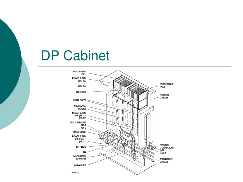
DP Cabinet. DP Cabinet. The DPC 21 (Dynamic Position Cabinet) comprises two identical computer, each with its I/O System. The cabinet comprises two areas: Process cabinet Termination cabinet. DPC Cabinet. Process Cabinet.

E N D
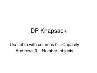
DP Cabinet • The DPC 21 (Dynamic Position Cabinet) comprises two identical computer, each with its I/O System. • The cabinet comprises two areas: • Process cabinet • Termination cabinet
Process Cabinet • Inside we will found the power supply, that provides a conversion from 220/230 Vac to 24 Vdc. This voltage will be distributed in the process cabinet. • In the process cabinet each “user” is protected with a fuse.
Process Cabinet • A filtering system is installed before the AC/DC conversion to prevent current spikes and environmental disturbs.
Process Cabinet • The Process cabinet comprises two card-rack, filled with the I/O interfaces. • Each card-rack contains a BP-407S backplane which provides connectors for cards and cables.
Process Cabinet • The normal configuration for the card-rack comprises the following I/O cards. • DI 400 (32 digital input channels) • AI 400 (32 analogue input channels) • AOV 406 (26 analogue input and 6 analogue output channels)
Process Cabinet • The serial line interface unit (TBSS) is used with up to two plug-in unit installed on it. • Each unit can handle the RS-232, the RS-422 and the current loop protocol.
Process Cabinet • In a dual redundant system the thrusters are grouped into two independent groups.Each computer has two AOV-406, one for each group, in order to make the correct I/O signals.
SBC 500 The Single Board Computer 500 is a real time computer for control process purpose, based on the Motorola MPC755 RISC processor at 300 MHz.
SBC 500 The SBC 500 perform the main task of DP system, included the Vessel Model. In the DP OS only the GUI is executed.
SBC 500 • The SBC 500 main bus is the PBUS (Process BUS), also called PBUS2 on the new versions. • Four alarm are provided: • Power under voltage • Fan not running • High Temperature • WatchDog timeout
SBC 500 The front panel provides the following functions: • Reset • NMI • Mode • RS-232 Console • LED Indicators
AI-400 • The AI-400 is an interface between the PBUS2 and 32 analogue inputs. • The input range is ± 10 Vdc • Each input is provided by a low pass filter • There are no configurable parts on the AI 400 card.
AI-400 Can receive up to 32 voltage signals from the field. It low-pass filters the signals and then guides them one at the time through the Analogue Multiplexers for A/D conversion. When the SBC performs a read-channel-x instruction and the card address comparator in the PLD respond with ‘match’, the channel x value is multiplexed through the Analogue Multiplexers, A/D converted and enebled to the bus as a 16 bit word through the Output data buffer to the PBUS2. The SBC reads one value at the time from AI 400 by addressing the card and one specific card device. The card device can either be one of the 32 channels or one of several registers in the Register and Control Logic PLD.
DI-400 • The DI-400 is an interface between the PBUS2 and 32 digital inputs. It low-pass filters the signals and saves them in two 16 bit registers on the card. • An optocoupler is included for each channel to isolate the field and the SBC side from each other. • There are no configurable parts on the DI 400 card.
AOV-406 • The AOV 406 card is an interface between the Process Bus (PBUS2), and 26 single-ended analogue input and 6 single-ended analogue output channels.
AOV-406 - Fail-safe outputs The fail-safe mechanism has two levels for this card. They are: • If contact with the SBC is lost, but the card itself functions OK, the PLD watch dog is triggered and forces the fail-safe values initially programmed to be set out by the micro-controller. The fail-safe values may be programmed for each channel and can be: - the last received and accepted values from the SBC. - 0 Vdc. • If the refresh mechanism on the card is defect, the refresh watch dog opens the analogue switches and set all outputs to 0 Vdc.
AOV-406 Configuration • The DIP-switch S1 bit 1, 2 and 3 are used to set the operational mode of the card. Bit 4 of the DIP-switch is not used.
OK/error indicationAI 400 – DI 400 – AOV 406 • A bi-colour (red/green) LED on the front of the card indicates the status of the card. A watch dog, controlled from the SBC, drives the LED. • Green light indicates that the SBC sends module-alive messages to the card. This means that the SBC can see no error with this card. In a system with no errors all the I/O card LEDs light green. • Red light indicates that the card is not running in the system. The reason for the red light can be: • the SBC has stopped. • the watch dog on the card has timed out. • the SBC has discovered a self diagnostics error on the I/O card and sends a module error messages to it that turns on the red LED.