Download
1 / 4
100 likes | 439 Views
Logical Effort and Transistor Sizing. Digital designs are usually expected to operate at high frequencies, thus designers often have to choose the fastest circuit topology and gate sizes for a particular logic function.

E N D
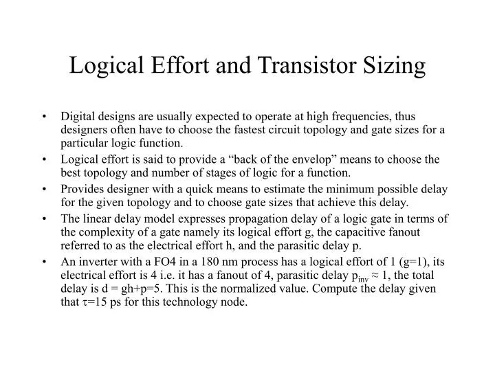
Logical Effort and Transistor Sizing • Digital designs are usually expected to operate at high frequencies, thus designers often have to choose the fastest circuit topology and gate sizes for a particular logic function. • Logical effort is said to provide a “back of the envelop” means to choose the best topology and number of stages of logic for a function. • Provides designer with a quick means to estimate the minimum possible delay for the given topology and to choose gate sizes that achieve this delay. • The linear delay model expresses propagation delay of a logic gate in terms of the complexity of a gate namely its logical effort g, the capacitive fanout referred to as the electrical effort h, and the parasitic delay p. • An inverter with a FO4 in a 180 nm process has a logical effort of 1 (g=1), its electrical effort is 4 i.e. it has a fanout of 4, parasitic delay pinv ≈ 1, the total delay is d = gh+p=5. This is the normalized value. Compute the delay given that =15 ps for this technology node.
Delay in Multistage Logic Network • Logical effort is not dependent on device size, on the other hand electrical effort is dependent on transistor sizes. • The logical effort of several gates in the data path can be expressed as the product of the logical efforts of each stage along the path G = ∏gi • The path electrical effort H can be given as the ratio of the output capacitance the path must drive divided by the input capacitance presented by the path. • The expression for path electrical effort is: H = Cout_path/Cin_path. • The path effort F is the product of the stage efforts of each stage F = ∏fi • If a path has branches F ≠ GH • To compute linear delays for paths that have branches a new term is introduced. The branching effort b is the ratio of the total capacitance seen by a stage to the capacitance on the path given by: b = [Con_path + Coff_path]/Con_path
Delay in Multistage Logic Network • The path branching effort B is the product of the branching efforts between stages given by: B = ∏bi • The path effort F can now be defined as a product of logical, electrical, and branching efforts of the path. • The product of the electrical efforts of the stages is BH and not just H, therefore F = GBH • The delay path D of a multistage network is the sum of the delays of each stage: D = ∑di =DF + P where DF = ∑fi and P = ∑pi • The products of the stage efforts is F, and independent of gate sizes. • The path effort delay is the sum of the stage efforts • If a path has N stages and each carrying the same effort we have that f=gihi=F1/N • The minimum possible delay of an N stage path with effort F and path parasitic delay P is given by D = F1/N + P
Choosing the Best Number Of Stages • The linear delay estimation equations allow us to approximate circuit topology delays and be able to chose gate sizes. • From logical effort examination we are in a position to see that NOR gates have poor (larger) delays compared to NAND gates. • Logical effort can also be used to predict the best number of stages to use. • In general inverters can be added at the end of a path to enable driving large loads. • The question is how many inverters can be added for least delay. • Starting with a path with n1 stages and a path effort of F, add N-n1 inverters to the end to bring the path to N stages. • The additional inverters do not change the path logical effort but do add parasitic delay and the new delay expression is: D = NF1/N+∑pi+(N-n1)pinv • The summation of the above expression is from i=1to n1.