Download
1 / 23
260 likes | 457 Views
Lunar Fission Surface Power Design - Relap5 Point Kinetics. D. S. Lucas INL. November, 2008. Acknowledgements. Jim Werner, INL Space Rx Lead Juan Carbajo, Lou Qualls ORNL Relap5 Model Dave Poston LANL MCNP Reactivity Coefficients, FRINK Rich Riemke, INL R5 Code Development

E N D
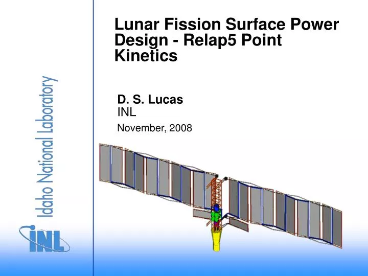
Lunar Fission Surface Power Design - Relap5 Point Kinetics D. S. Lucas INL November, 2008
Acknowledgements • Jim Werner, INL Space Rx Lead • Juan Carbajo, Lou Qualls ORNL Relap5 Model • Dave Poston LANL MCNP Reactivity Coefficients, FRINK • Rich Riemke, INL R5 Code Development • Cliff Davis, INL R5 Code Development & Modeling
Discussion • Brief Background • Deliverables • Model Responsibilities • Why Modeling and Simulation • LANL,SNL,ORNL,INL Models • Reactor Kinetics Importance • SQA • Summary and Recommendations
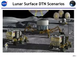
Background • Fast Reactor on Moon for Colony • Solar – Not enough Power • Rx - 180 KW Thermal • 40 kW(e) Net Reactor Power • 8 full-power years • Meet allowable dose levels • Meet launch loads • Operate in lunar environment • Minimum reactor module mass and launch envelope • Meet safety and safeguards requirements • Meet reliability requirements
Design Parameters • Fast reactor (Cat II) • NaK coolant • Open lattice core configuration • Stainless steel reactor structure (SS-316) • UO2 fuel • BeO axial reflectors, Be radial reflector • B4C in Radial Reflector Shim for reactivity control • Coolant T-in = 850-900 K, T-out =900-950 K (Subject to Change)
Pre-Decisional Deliverables • Concept Trade Study • Pre-conceptual Design • Conceptual Design • System models and tools • System reliability assessment • Demonstration of key technology • Fuel (vendor needed to meet Phase B/C/D schedule) • EM pump • I&C • (drum / sliders – motors, bearings, sensors) • Others? • Safety assurance (INSRP) strategy • Design and fabrication of components for TDU
Responsibilities • LANL Overall Core Design • ORNL Controllers, Heat Exchangers • INL E&M Pumps, Backup TDU Simulator & Kinetics • Argonne East – SASYS Model • SANDIA – Simulink TDU Simulator • Need Modeling and Simulation to combine with zero power critical tests and non-nuclear full scale system tests
FPS Schematic 4 x 12 kWe 400Vac Pwr Cond & Cont Trad=382K PLR Rad1 (66 kWt) Rad2 100 m Tcold=425K PS2 PS4 Bus (270Vdc) H2O Tin,rad=413K dT=25K Stir2* Stir4* Aux Loads (5 kW) User Loads (40 kW) Commands Telemetry PS1 PS3 Stir1* Stir3* Battery (10 kWh) NaK Tin,pc=825K dT=30K Thot=791K Solar Array (5 kWe) PI1 PI2 IHX1 IHX2 NaK Tout,rx=850K dT=50K Rx (183 kWt) PP2 PP1 Tclad=860K * Each Stirling converter includes two linear alternators.
ORNL Relap5 ModelJuan Carbajo - Modeling and Analysis of a Lunar Space Reactor – ICAPP - 08
Pzr EM Pmp Sec EM PumpNaK H2O Pmp H2O Rad Out SHot SCold Reactor Core VP In LANL FRINK & INL R5 TDU/Simulator Model – Put Reactivity Coefficients in ORNL Model
Reactivity Data • LANL MCNP ran with different material temperatures • Keff’s Computed • Contributions from Fuel, Moderator, Clad, Shields • Data to R5 Format, Additional Heat Structures for SS Liner, Be Reflector, B4C Shield • All Shields to be done with R5 Envelope Model • Feedback from R5 to Neutronics Important • ORNL Steady State with Neutronics • Pump Trip Case with/without Shield with Neutronics • Pump Trip at 200 seconds • Simulation on PC out to 600 seconds
Pre-Conceptual Results • Pumps Trip – With and without Radial B4C Shield • Secondary Pump Trip • Primary Half Flow
Conclusions & Future Tasks • Model - Testing Heat Structures, Core Kinetics • Run Limited Transients • Nestle- Explain? • Attila – SW Model Check Rx Coefficients • Independent Review & Document Kinetics • Give to Sandia & ORNL • Checking New Geometry Data • SQA Plan – Transients • Couple R5 to NASA Glenn Stirlings via Model Center