Download
1 / 28
280 likes | 386 Views
High-Level Spectral ATPG for Gate-level Circuits. Nitin Yogi and Vishwani D. Agrawal Auburn University Department of ECE Auburn, AL 36849. Outline. Need for High Level Testing Problem and Approach Spectral analysis and generation of test sequences RTL testing approach

E N D
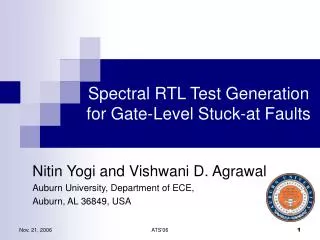
High-Level Spectral ATPGfor Gate-level Circuits Nitin Yogi and Vishwani D. Agrawal Auburn University Department of ECE Auburn, AL 36849 Spectral RTL ATPG
Outline • Need for High Level Testing • Problem and Approach • Spectral analysis and generation of test sequences • RTL testing approach • Experimental Results • Conclusion • Future work • Research Goals Spectral RTL ATPG
Need for High Level Testing Seems interesting ! But is it feasible ? • Motivations for high level testing: • Low testing complexity • Low testing times and costs • Early detection of testability issues during design phase at high level or RTL • Difficulty of gate-level test generation for black box cores with known functionality Spectral RTL ATPG
Problem and Approach That’s fine ! But does it work ? • What’s the problem ? • Develop synthesis-independent ATPG methods using RTL circuit description. • How do we approach it ? • Implementation-independent characterization: • RTL test generation • RTL faults => PI, PO and inputs and outputs of flip-flops • Generate vectors for RTL faults • Analyze RTL vectors to extract spectral components and the noise level for each PI of the circuit. • Test generation for a gate-level implementation using RTL characterization: • Generation of test vectors • Test vector compaction Spectral RTL ATPG
Walsh Functions and Hadamard Spectrum OK…so its just another way of representing information w0 • Walsh functions form an orthogonal and complete set of functions representing a discretized function. • Walsh functions form the rows of the Hadamard matrix; called its basis vectors. • Example of Hadamard matrix of order 8: w1 w2 w3 Walsh functions (order 8) H8 = 1 1 1 1 1 1 1 1 1 -1 1 -1 1 -1 1 -1 1 1 -1 -1 1 1 -1 -1 1 -1 -1 1 1 -1 -1 1 1 1 1 1 -1 -1 -1 -1 1 -1 1 -1 -1 1 -1 1 1 1 -1 -1 -1 -1 1 1 1 -1 -1 1 -1 1 1 -1 w4 w5 w6 w7 Spectral RTL ATPG
Analysis of a Bit Stream Using Hadamard Matrix • Bit stream is correlated with each basis vector of the Hadamard matrix. • High correlated basis vectors are retained as essential components and others are regarded as noise. • New bit streams can be generated keeping the essential components and eliminating or changing the noise components. Bit stream to analyze Correlating with basis vectors by multiplying with Hadamard matrix. Bit stream Spectral coeffs. Essential component (others noise) Hadamard Matrix Spectral RTL ATPG
Test Vector Generation OK…so you are refining the bit stream • The components regarded as noise are filtered or altered as per a methodology. • The filtered components are converted back to a test vector by multiplying with Hadamard matrix Filtering Spectral components Generation of test vectors by multiplying with Hadamard matrix Essential component retained New test vector Spectral RTL ATPG
RTL Testing Approach (Circuit Characterization) • RTL test generation: • Test vectors are generated for RTL faults (PI, PO and inputs - outputs of flip-flops.) • Spectral analysis: • Test sequences for each input are analyzed using Hadamard matrix. • Essential components are currently determined by comparing their magnitudes Hi with the mean of the total spectrum M. • Condition to pick-out essential components: • The process starts with the highest magnitude component and is repeated till the criteria is not satisfied. Spectral RTL ATPG
Circuit b01: Coefficient Analysis (Vectors for RTL faults obtained from delay optimized circuit) Magnitudes of 32 Hadamard Coeffs. for 3 inputs of b01 Examples of noise components Examples of essential components Spectral RTL ATPG
RTL Testing Approach (Test vector generation) • Spectral Test Vector Generation: • Perturbation of spectral coefficients • Retain essential spectral components • Add random noise to replace the original identified noise. • Components considered non-essential are changed randomly both in magnitude and sign in a confined confidence level. • Generation of test vectors. Spectral RTL ATPG
RTL Testing Approach (Test vector generation) OK…I got that….. What about the RESULTS !!! • Test Vector Compaction: • Characteristics of generated vectors depend on inserted noise. • Characteristics determine the fault coverage, the detectability of hard to detect faults, etc. • 10 test sets are generated using the spectral method and compacted to achieve the best fault coverage. • Compaction currently performed by simple fault simulation of generated test sets on the target gate-level implementation. Spectral RTL ATPG
Experimental Results • Spectral ATPG technique was applied to three ITC’99 high level RTL benchmark circuits, b01, b09 and b11 • Characteristics of benchmark circuits: • The benchmark circuits synthesized in two ways: • optimizing area • optimizing delay. • Vectors for RTL faults obtained from ATPG (FlexTest). • Spectral RTL-ATPG technique applied to the circuits. Spectral RTL ATPG
RTL Spectral Characterization: b01 * Sun Ultra 5, 256MB RAM Spectral RTL ATPG
Gate-Level Test Generation: b01 * Sun Ultra 5, 256MB RAM Spectral RTL ATPG
Gate-Level Cov. of Spectral Test Sets on Area-Optimized b01 Circuit Spectral RTL ATPG
Gate-Level Cov. of Spectral Test Sets on Delay-Optimized b01 Circuit Spectral RTL ATPG
RTL Spectral Characterization: b09 * Sun Ultra 5, 256MB RAM Spectral RTL ATPG
Gate-Level Test Generation: b09 * Sun Ultra 5, 256MB RAM Spectral RTL ATPG
Gate-Level Cov. of Spectral Test Sets on Area-Optimized b09 Circuit Spectral RTL ATPG
Gate-Level Cov. of Spectral Test Sets on Delay-Optimized b09 Circuit Spectral RTL ATPG
RTL Spectral Characterization: b11 * Sun Ultra 5, 256MB RAM Spectral RTL ATPG
Gate-Level Test Generation: b11 * Sun Ultra 5, 256MB RAM Spectral RTL ATPG
Gate-Level Cov. of Spectral Test Sets on Area-Optimized b11 Circuit Spectral RTL ATPG
Gate-Level Cov. of Spectral Test Setson Delay-Optimized b11 Circuit Hmmm… interesting ! Spectral RTL ATPG
Conclusion • Spectral RTL ATPG technique was applied to ITC’99 benchmark circuits b01, b09 and b11 and found to give favorable results in two out of the three circuits. • Results indicate promise in further development of Spectral RTL ATPG technique. • Test generation using Spectral RTL ATPG brings with it all the benefits of high level testing • Techniques that will enhance Spectral ATPG are: • Efficient RTL ATPG • Accurate determination of noise components • Better ways of random noise insertion with more control over noise inserted • Better compaction algorithms Spectral RTL ATPG
Future Work Analytical model • Model the test generation system in the frequency domain using transfer functions. • Finding the relationship • Characterize input random vectors and output RTL vectors in the frequency domain • Obtain the transfer function for the Test generation system to target gate level faults • Challenges in frequency domain • Linearity • Time-invariance • Possible tools for frequency analysis: • Walsh functions • FFT ATPG Test vectors Random vecs. Circuit under test Test generation system Spectral RTL ATPG
Research Goals • Extraction of spectral components from functional vectors and their application for test generation. • Theoretical analysis of spectral components and the noise level. • Consideration of both temporal and spatial spectra using two-dimensional signal analysis. • Application to combinational and sequential circuits. • Use of improved test generation for RTL faults. • Effective application of vector compaction methods. Spectral RTL ATPG
Thank You ! Any Questions ? Spectral RTL ATPG