Download
1 / 51
510 likes | 642 Views
Files. Secondary Storage and System Software: Magnetic Disks &Tapes. Part I: Disks Outline. The Organization of Disks Estimating Capacities and Space Needs Organizing Tracks by Sector Organizing Tracks by Block Non Data Overhead The Cost of a Disk Access

E N D
Files Secondary Storage and System Software: Magnetic Disks &Tapes
Part I: Disks Outline • The Organization of Disks • Estimating Capacities and Space Needs • Organizing Tracks by Sector • Organizing Tracks by Block • Non Data Overhead • The Cost of a Disk Access • Disk as Bottleneck
General Overview Having learned how to manipulate files, we now learn about the nature and limitations of the devices and systems used to store and retrieve files, so that we can design good file structures that arrange the data in ways that minimize access costs given the device used by the system.
Disks: An Overview • Disks belong to the category of Direct Access Storage Devices (DASDs) because they make it possible to access the data directly. • This is in contrast to Serial Devices (e.g., Magnetic Tapes) which allows only serial access [all the data before the one we are interested in has to be read or written in order]. • Different Types of Disks: • Hard Disk: High Capacity + Low Cost per bit. • Floppy Disk: Cheap, but slow and holds little data. (zip disks: removable disk cartridges) • Optical Disk (CD-ROM): Read Only, but holds a lot of data and can be reproduced cheaply. However, slow.
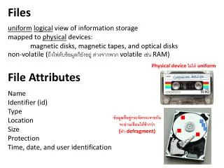
The Organization of Disks I • The information stored on a disk is stored on the surface of one or more platters. See next slide. • The information is stored in successive tracks on the surface of the disk. See second slide from this one. • Each track is often divided into a number of sectors which is the smallest addressable portion of a disk.
The Organization of Disks II • When a read statement calls for a particular byte from a disk file, the computer’s operating system finds the correct platter, track and sector, reads the entire sector into a special area in memory called a buffer, and then finds the requested byte within that buffer.
The Organization of Disks III • Disk drives typically have a number of platters and the tracks that are directly above and below one another form a cylinder. (See next slide) • All the info on a single cylinder can be accessed without moving the arm that holds the read/write heads. • Moving this arm is called seeking. The arm movement is usually the slowest part of reading information from a disk.
Disks ranges in width from 2 to 14 inches, commonly 3.5”. • The capacity of a disk ranges from several megabytes to several hundreds of gigabytes. • In a disk, each platters can store data on both sides, called surfaces. • The number of surfaces is twice the number of platters. • The number of cylinders is the same as the number of tracks on a single surface. • The bit density on a track affects the amount of data can be held on the track surface. The bit density depends on the quality of the recording medium and the size of the read/write head. • A low density disk can hold about 4KB on a track and 35 tracks on a surface. • A top-of-the-line disk can hold more than 1MB on a track and more than 10,000 tracks on a surface (cylinders).
Estimating Capacities and Space Needs • Track Capacity = number of sectors per track * bytes per sector • Cylinder Capacity = number of tracks per cylinder * track capacity • Drive Capacity = number of cylinders * cylinder capacity
Data Organization: I. Organizing Tracks per Sector • The Physical Placement of Sectors • The most practical logical organization of sectors on a track is that sectors are adjacent, fixed-sized segments of a track that happens to hold a file. • Physically, however, this organization is not optimal: after reading the data, it takes the disk controller some time to process the received information before it is ready to accept more. If the sectors were physically adjacent, we would use the start of the next sector while processing the info just read in.
Two basic ways to organize data on a disk: • organizing tracks by sector, and • organizing tracks by user-defined block. • The physical placement of sectors: • physically adjacent sectors • interleaving sectors For newer disks with faster data transfer rate For disks with slow data transfer rate
Data Organization: I. Organizing Tracks per Sector (Cont’d) • Traditional Solution:Interleave the sectors. Namely, leave an interval of several physical sectors between logically adjacent sectors. • Nowadays, however, the controller’s speed has improved so that no interleaving is necessary anymore.
Data Organization:I. Organizing Tracks by Sectors (Cont’d) • The file can also be viewed as a series of clusters of sectors which represent a fixed number of (logically) contiguous sectors. • A cluster is a fixed number of contiguous sectors (not physically contiguous; the degree of physical contiguity is determined by the interleaving factor). • Once a cluster has been found on a disk, all sectors in that cluster can be accessed without requiring an additional seek.
The File Allocation Table ties logical sectors to the physical clusters they belong to. • The system administrator can decide how many sectors in a cluster.
Data Organization:I. Organizing Tracks by Sectors (Cont’d) • If there is a lot of free room on a disk, it may be possible to make a file consist entirely of contiguous clusters. ==> the file consists of one extent. ==> the file can be processed with a minimum of seeking time. • If one extent is not enough, then divide the file into more extents. • As the number of extents in a file increases, the file becomes more spread out on the disk, and the amount of seeking necessary increases.
Internal fragmentation of a disk is the unused disk space which cannot be used by other files. • Store a file of 300-byte records in a disk of sector size 512 bytes. • Store a record in a sector. This will cause the loss of disk space, i.e., internal fragmentation. • Allow records to span in two sectors. This will save disk space. But, it may require the retrieval of two sectors when accessing a record.
If the number of bytes in a file is not a multiple of the cluster size, internal fragmentation will occur in the last extent of the file.
Data Organization:I. Organizing Tracks by Sectors (Cont’d) • There are 2 possible organizations for records (if the records are smaller than the sector size: 1. Store 1 record per sector 2. Store the records successively (i.e., one record may span two sectors
Data Organization:I. Organizing Tracks by Sectors (Cont’d) • Trade-Offs • Advantage of 1: Each record can be retrieved from 1 sector. • Disadvantage of 1: Loss of Space with each sector ==> Internal Fragmentation • Advantage of 2: No internal fragmentation • Disadvantage of 2: 2 sectors may need to be accessed to retrieve a single record. • The use of clusters also leads to internal fragmentation.
Data Organization: II. Organizing Tracks by Block • Rather than being divided into sectors, the disk tracks may be divided into user-defined blocks. • When the data on a track is organized by block, this usually means that the amount of data transferred in a single I/O operation can vary depending on the needs of the software designer (not the hardware). • Blocks can normally be either fixed or variable in length, depending on the requirements of the file designer and the capabilities of the operating system.
Data Organization: II.Organizing Tracks by Block (Cont’d) • Blocks don’t have the sector-spanning and fragmentation problem of sectors since they vary in size to fit the logical organization of the data. • The term blocking factor indicates the number of records that are to be stored in each block in a file. • Each block is usually accompanied by subblocks: key-subblock or count-subblock.
subblocks: key-subblock or count-subblock. • Count subblock – contains the number of bytes in the accompanying data block • Key subblock allow the disk controller to search a track for a block or record identified by a given key • IE a key search
Non-Data Overhead I • Whether using a block or a sector organization, some space on the disk is taken up by non-data overhead. i.e., information stored on the disk during pre-formatting. • On sector-addressable disks, pre-formatting involves storing, at the beginning of each sector, sector address, track address and condition (usable or defective) + gaps and synchronization marks between fields of info to help the read/write mechanism distinguish between them. • On Block-Organized disks, subblock + interblock gaps have to be provided with every block. The relative amount of non-data space necessary for a block scheme is higher than for a sector-scheme.
Non-Data Overhead II • The greater the block-size, the greater potential amount of internal track fragmentation. (At the end of the track) • The flexibility introduced by the use of blocks rather than sectors can save time since it lets the programmer determine, to a large extent, how the data is to be organized physically on disk. • Overhead for the programmer and Operating System. • Can’t synchronize I/O operation with movement of disk.
The Cost of a disk Access • Seek Time is the time required to move the access arm to the correct cylinder. • Rotational Delay is the time it takes for the disk to rotate so the sector we want is under the read/write head. • Transfer Time = (Number of Bytes Transferred/ Number of Bytes on a Track) * Rotation Time
Suppose the previous mentioned disk (256 sectors) with 10000 rpm (resolutions per minute) average seek time = 10 ms average rotational delay = half resolution = (1/2) (1/10000) minute = 3 ms • Suppose the previous mentioned file is stored as Case 1. Random sectors, that is, we can read only one sector a time Case 2. Random clusters: each cluster has 8 sectors (4KB). Case 3.One extent Decide the access time of the file for these three cases
Case 1: assume the file is read sector by sector in random. average seek 10.0 msec rotational delay 3.0 msec read one sector 0.023 msec //(1/256) (1/10000 min) Total 13.023 msec Total time =250000 13.023 msec = 3255.75 seconds = 54 minutes • Case 2: assume the file is read cluster by cluster in random. average seek 10.0 msec rotational delay 3.0 msec read one cluster 0.187 msec //(8/256) (1/10000 min) total 13.187 msec Total time: (250000/8) 13.187 msec = 412.09 seconds = 6.9 minutes
Case 3: sequential access average seek 10.0 msec 41 = 410 msec rotational delay 3 msec read one extend (250000/256) (1/10000 min) = 5859.4 msec Total time: 410 + 3 + 5859.4 = 6272.4. msec = 6.3 seconds • Conclusion • Seeking is the most expensive operation. Avoid seeking as much as possible. • Grouping data into larger units (e.g., cluster) can reduce access time. • Sequential access is much faster than random access.
Disk as Bottleneck I • Processes are often Disk-Bound, i.e., the network and the CPU often have to wait inordinate lengths of time for the disk to transmit data. • Solution 1: Multiprogramming (CPU works on other jobs while waiting for the disk) • Solution 2: Stripping: splitting the parts of a file on several different drives, then letting the separate drives deliver parts of the file to the network simultaneously ==> Parallelism
Disk as Bottleneck II • Solution 3: RAID: Redundant Array of Independent Disks • Solution 4: RAM disk ==> Simulate the behavior of the mechanical disk in memory. • Solution 5: Disk Cache= large block of memory configured to contain pages of data from a disk. Check cache first. If not there, go to the disk and replace some page already in cache with page from disk containing the data.
Tape • No direct accessing facility, but very rapid sequential access. • Compactness, resistance to rough environmental conditions, easy to store and transport, cheaper than disk • Used to be used for application data • Currently, tapes are primarily used as archival storage.
Organization of Data on Nine-Track Tapes • On a tape, the logical position of a byte within a file corresponds directly to its physical position relative to the start of the file. • The surface of a typical tape can be seen as a set of parallel tracks each of which is a sequence of bits. These bits correspond to 1 byte + a parity bit. (See page 68) • One Byte = a one-bit-wide slice of tape called a frame. • In odd parity, the bit is set to make the number of bits in the frame odd. This is done to check the validity of the data. • Frames are organized into data blocks of variable size separated by interblock gaps (long enough to permit stopping and starting)
Estimating Tape Length Requirements • Let b= the physical length of a data block • Let g= the length of an interblock gap, and • Let n= the number of data blocks. • The space requirement, s, for storing the file is s = n (b+g) • b= blocksize (i.e., bytes per block)/ tape density (i.e., bytes per inch) • The number of records stored in a physical block is called the blocking factor. • Effective Record Density: a general measure of the effect of choosing different block sizes: (number of bytes per block)/ (number of inches required to store a block) • ==> Space utilization is sensitive to the relative sizes of data blocks and interblock gaps.
Estimating Data Transmission Times • Normal Data Transmission Rate= (Tape Density (bpi)) (Tape Speed (ips)) • Interblock gaps, however, must be taken into consideration Effective Transmission Rate = (Effective Recording Density) (Tape Speed) • Blocking factor affects effective transmission rate.
Disk versus Tape • In the past: • Both Disks and Tapes were used for secondary storage. Disks were preferred for random access and tape was better for sequential access. • Now: • Disks have taken over much of secondary storage ==> Because of the decreased cost of disk + memory storage • Tapes are used as Tertiary storage (Cheap, fast & easy to stream large files or sets of files between tape and disk)
CD-ROM • A single disc can hold more than 600 MB of data. • CD-ROM is a descendent of CD Audios. i.e., listening to music is sequential and does not require fast random access to data. • CD-ROM is read only. i.e., it is a publishing medium rather than a data storage and retrieval like magnetic disks. There can’t be any changes ==> File organization can be optimized. • CD-ROM Strengths: • High storage capacity • Inexpensive price • Durability • CD-ROM Weaknesses: • Extremely slow seek performance (between 1/2 a second to a second) ==> Intelligent File Structures are critical.
Pits and Lands • CD-ROMs are stamped from a glass master disk which has a coating that is changed by the laser beam. When the coating is developed, the areas hit by the laser beam turn into pits along the track followed by the beam. The smooth unchanged areas between the pits are called lands. • Pits scatter light; lands reflect light. • 1’s are represented by the transition from pit to land and back again. 0’s are represented by the amount of time between transitions. The longer between transitions, the more 0s we have.
There must be at least two 0s between any pair of 1s. • Raw patterns of 1s and 0s have to be translated to get the 8-bit patterns of 1s and 0s that form the bytes of the original data. • EFM encoding (Eight to Fourteen Modulations) turns the original 8 bits of data into 14 expanded bits that can be represented in the pits and lands on the disk. • Since 0s are represented by the length of time between transition, the disk must be rotated at a precise and constant speed. This affects the CD-ROM drive’s ability to seek quickly.
CLV vs. CAV • Data on a CD-ROM is stored in a single, spiral track. This allows the data to be packed as tightly as possible since all the sectors have the same size (whether in the center or at the edge) -- constant linear velocity (CLV). • Since reading the data requires that it passes under the optical pick-up device at a constant rate, the disc has to spin more slowly when reading the outer edges than when reading towards the center.
The CLV format is responsible for the poor seeking performance of CD-ROM Drives: there is no straightforward way to jump to a location. Part of the problem is the need to change rotational speed. • To read the address info, we need to be moving the data under the optical pick up at the correct speed. But to adjust the speed, we need to read the address info. How do we break this loop? By guessing and through trial and error ==> Slows down performance. • Disk drives pack the data more densely in the center than in the edge -- constant angular velocity (CAV). The disk spins at a constant rate. Data density is less on outer tracks. It is easy to find the start of a tractor.
Addressing • Different from the “regular” disk method. • Each second of playing time on a CD is divided into 75 sectors. Each sector holds 2 Kilobytes of data. Each CD-ROM contains at least one hour of playing time. The disc is capable of holding at least 60 min * 60 sec/min * 75 sector/sec * 2 Kilobytes/sector = 540, 000 KBytes • Often, it is actually possible to store over 600, 000 KBytes. • Sectors are addressed by min:sec:sector e.g., 16:22:34
A Journey of A Byte What happens when the program statement: write(fd, &ch, 1) is executed ? Part that takes place in memory: • Statement calls the Operating System (OS) which overseas the operation • File manager (Part of the OS that deals with I/O) • Checks whether the operation is permitted • Locates the physical location where the byte will be stored (Drive, Cylinder, Track & Sector) • Finds out whether the sector to put the character is already in memory (if not, call the I/O Buffer) • Puts ‘P’ (content of ch) in the I/O Buffer • Keep the sector in memory to see if more bytes will be going to the same sector in the file
A Journey of A Byte (Cont’d) Part that takes place outside of memory: • I/O Processor: Wait for an external data path to become available (CPU is faster than data-paths ==> Delays) • Disk Controller: • I/O Processor asks the disk controller if the disk drive is available for writing • Disk Controller instructs the disk drive to move its read/write head to the right track and sector. • Disk spins to right location and byte is written
Buffer Management • What happens to data travelling between a program’s data area and secondary storage? • Buffering involves working with a large chunk of data in memory so the number of accesses to secondary storage can be reduced. • How many buffers do we need? at least two: one for input and the other for output • Moving data to or from disk is very slow and programs may become I/O bound.