Download

1 / 48
480 likes | 581 Views
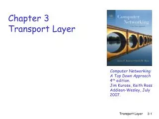
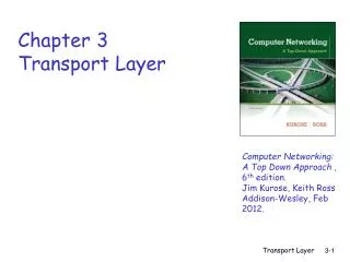
CSCI 3335: Computer Networks Chapter 3 Transport Layer. Vamsi Paruchuri University of Central Arkansas http://faculty.uca.edu/vparuchuri/3335.htm. Some of the material is adapted from J.F Kurose and K.W. Ross. 3.1 Transport-layer services 3.2 Multiplexing and demultiplexing

E N D
CSCI 3335: Computer Networks Chapter 3 Transport Layer Vamsi Paruchuri University of Central Arkansas http://faculty.uca.edu/vparuchuri/3335.htm Some of the material is adapted from J.F Kurose and K.W. Ross
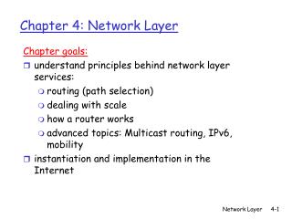
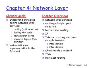
3.1 Transport-layer services 3.2 Multiplexing and demultiplexing 3.3 Connectionless transport: UDP 3.4 Principles of reliable data transfer 3.5 Connection-oriented transport: TCP segment structure reliable data transfer flow control connection management 3.6 Principles of congestion control 3.7 TCP congestion control Chapter 3 outline TransportLayer
full duplex data: bi-directional data flow in same connection MSS: maximum segment size connection-oriented: handshaking (exchange of control msgs) inits sender, receiver state before data exchange flow controlled: sender will not overwhelm receiver point-to-point: one sender, one receiver reliable, in-order byte steam: no “message boundaries” pipelined: TCP congestion and flow control set window size send & receive buffers TCP: OverviewRFCs: 793, 1122, 1323, 2018, 2581 TransportLayer
32 bits source port # dest port # sequence number acknowledgement number head len not used Receive window U A P R S F checksum Urg data pnter Options (variable length) application data (variable length) TCP segment structure URG: urgent data (generally not used) counting by bytes of data (not segments!) ACK: ACK # valid PSH: push data now (generally not used) # bytes rcvr willing to accept RST, SYN, FIN: connection estab (setup, teardown commands) Internet checksum (as in UDP) TransportLayer
32 bits source port # dest port # sequence number acknowledgement number head len not used Receive window U A P R S F checksum Urg data pnter Options (variable length) application data (variable length) TCP segment structure - Quiz • What is the significance of each field • What is TCP Header size • What is max Receiver Window Size? Is it large enough? • Which field should be larger “Seq#” or “Receive window”? Why? • What is the maximum # options? • Which flags are set in first message in connection set up? Second message? Third message? • Why are initial Seq # set randomly? Flags: SYN, FIN, RESET, PUSH, URG, ACK TransportLayer
TCP Header: Flags (6 bits) • Connection establishment/termination • SYN – establish; sequence number field contains valid initial sequence number • FIN - terminate • RESET - abort connection because one side received something unexpected • PUSH - sender invoked push to send • URG – indicated urgent pointer field is valid; special data - record boundary • ACK - indicates Acknowledgement field is valid 3: Transport Layer
TCP Header: ACK flag • ACK flag – if on then acknowledgement field valid • Once connection established no reason to turn off • Acknowledgment field is always in header so acknowledgements are free to send along with data 3: Transport Layer
TCP Header: PUSH • Intention: use to indicate not to leave the data in a TCP buffer waiting for more data before it is sent • Receiver is supposed to interpret as deliver to application immediately; most TCP/IP implementations don’t delay delivery in the first place though 3: Transport Layer
32 bits source port # dest port # sequence number acknowledgement number head len not used Receive window U A P R S F checksum Urg data pnter Options (variable length) application data (variable length) TCP Header: Header Length • Header Length (4 bits) • needed because options field make header variable length • Expressed in number of 32 bit words = 4 bytes • 4 bits field => 4 bytes*24 = 60 bytes; 20 bytes of required header gives 40 bytes possible of options • Recall UDP header was 8 bytes 3: Transport Layer
Implications of Field Length • 32 bits for sequence number (and acknowledgement); 16 bits for advertised window size • Implication for maximum window size? Window size <= ½ SequenceNumberSpace • Requirement easily satisfied because receiver advertised window field is 16 bits • 232 >> 2* 216 • Even if increase possible advertised window to 231 that would still be ok 3: Transport Layer
Implications of Field Length (cont) • Advertised Window is 16 bit field => maximum window is 64 KB • Is this enough to fill the pipeline? Not always • Pipeline = delay*BW product • 100 ms roundtrip and 100 Mbps => 1.19 MB 3: Transport Layer
TCP Header: Common Options • Options used to extend and test TCP • Each option is: • 1 byte of option kind • 1 byte of option length • Examples • window scale factor: if don’t want to be limited to 216 bytes in receiver advertised window • timestamp option: if 32 bit sequence number space will wrap in MSL; add 32 bit timestamp to distinguish between two segments with the same sequence number • Maximum Segment Size can be set in SYN packets 3: Transport Layer
TCP Connection Management Recall:TCP sender, receiver establish “connection” before exchanging data segments • initialize TCP variables: • seq. #s • buffers, flow control info (e.g. RcvWindow) • client: connection initiator Socket clientSocket = new Socket("hostname","port number"); • server: contacted by client Socket connectionSocket = welcomeSocket.accept(); Three way handshake: Step 1:client end system sends TCP SYN control segment to server • specifies initial seq # Step 2:server end system receives SYN, replies with SYNACK control segment • ACKs received SYN • allocates buffers • specifies server-> receiver initial seq. # Step 3: client acknowledges servers initial seq. # 3: Transport Layer
Active participant Passive participant (client) (server) SYN, SequenceNum = x , y 1 + SYN + ACK, SequenceNum = x Acknowledgment = SequenceNum = x+1 ACK, Acknowledgment = y + 1 Three-Way Handshake 3: Transport Layer
Connection Establishment • Both data channels opened at once • Three-way handshake used to agree on a set of parameters for this communication channel • Initial sequence number for both sides (random) • Receiver advertised window size for both sides • Optionally, Maximum Segment Size (MSS) for each side; if not specified MSS of 536 bytes is assumed to fit into 576 byte datagram 3: Transport Layer
Initial Sequence Numbers • Chosen at random in the sequence number space? • Well not really randomly; intention of RFC is for initial sequence numbers to change over time • 32 bit counter incrementing every 4 microseconds • Vary initial sequence number to avoid packets that are delayed in network from being delivered later and interpreted as a part of a newly established connection (to avoid reincarnations) 3: Transport Layer
Seq. #’s: byte stream “number” of first byte in segment’s data ACKs: seq # of nextbyte expected from other side cumulative ACK Q: how receiver handles out-of-order segments A: TCP spec doesn’t say, - up to implementor time TCP seq. #’s and ACKs Host B Host A User types ‘C’ Seq=42, ACK=79, data = ‘C’ host ACKs receipt of ‘C’, echoes back ‘C’ Seq=79, ACK=43, data = ‘C’ host ACKs receipt of echoed ‘C’ Seq=43, ACK=80 simple telnet scenario TransportLayer
Connection Termination • Each side of the bi-directional connection may be closed independently • 4 messages: FIN message and ACK of that FIN in each direction • Each side closes the data channel it can send on • One side can be closed and data can continue to flow in the other direction, but not usually • FINs consume sequence numbers like SYNs 3: Transport Layer
client server close FIN ACK close FIN ACK timed wait closed TCP Connection Management (cont.) Closing a connection: client closes socket:clientSocket.close(); Step 1:client end system sends TCP FIN control segment to server Step 2:server receives FIN, replies with ACK. Closes connection, sends FIN. 3: Transport Layer
3.1 Transport-layer services 3.2 Multiplexing and demultiplexing 3.3 Connectionless transport: UDP 3.4 Principles of reliable data transfer 3.5 Connection-oriented transport: TCP segment structure reliable data transfer flow control connection management 3.6 Principles of congestion control 3.7 TCP congestion control Chapter 3 outline TransportLayer
TCP creates rdt service on top of IP’s unreliable service pipelined segments cumulative acks TCP uses single retransmission timer retransmissions are triggered by: timeout events duplicate acks initially consider simplified TCP sender: ignore duplicate acks ignore flow control, congestion control TCP reliable data transfer TransportLayer
data rcvd from app: Create segment with seq # seq # is byte-stream number of first data byte in segment start timer if not already running (think of timer as for oldest unacked segment) expiration interval: TimeOutInterval timeout: retransmit segment that caused timeout restart timer Ack rcvd: If acknowledges previously unacked segments update what is known to be acked start timer if there are outstanding segments TCP sender events: TransportLayer
Host A Host B Seq=92, 8 bytes data ACK=100 Seq=92 timeout timeout X loss Seq=92, 8 bytes data ACK=100 time time lost ACK scenario TCP: retransmission scenarios Host A Host B Seq=92, 8 bytes data Seq=100, 20 bytes data ACK=100 ACK=120 Seq=92, 8 bytes data SendBase = 100 SendBase = 120 ACK=120 Seq=92 timeout SendBase = 100 SendBase = 120 premature timeout
Host A Host B Seq=92, 8 bytes data ACK=100 Seq=100, 20 bytes data timeout X loss ACK=120 time Cumulative ACK scenario TCP retransmission scenarios (more) SendBase = 120 TransportLayer
Q: how to set TCP timeout value? longer than RTT but RTT varies too short: premature timeout unnecessary retransmissions too long: slow reaction to segment loss Q: how to estimate RTT? SampleRTT: measured time from segment transmission until ACK receipt ignore retransmissions SampleRTT will vary, want estimated RTT “smoother” average several recent measurements, not just current SampleRTT TCP Round Trip Time and Timeout TransportLayer
TCP Round Trip Time and Timeout EstimatedRTT = (1- )*EstimatedRTT + *SampleRTT • Exponential weighted moving average • influence of past sample decreases exponentially fast • typical value: = 0.125 TransportLayer
Example RTT estimation: TransportLayer
time-out period often relatively long: long delay before resending lost packet detect lost segments via duplicate ACKs. sender often sends many segments back-to-back if segment is lost, there will likely be many duplicate ACKs. if sender receives 3 ACKs for the same data, it supposes that segment after ACKed data was lost: fast retransmit:resend segment before timer expires Fast Retransmit TransportLayer
Host A Host B Seq=92, 8 bytes data Seq=100, 20 bytes data X Seq=120, 20 bytes data ACK=100 Seq=140, 20 bytes data Seq=160, 20 bytes data ACK=100 ACK=100 ACK=100 resend 2nd segment: Seq=100, 20 bytes data timeout ACK=180 time Figure 3.37 Resending a segment after triple duplicate ACK TransportLayer
What are “Cumulative Acks”? What is advantage of having short time outs? What is advantage of having long time outs? Describe the method(s) TCP uses to detect packet losses. What is Fast Retransmit? TCP Quiz -2 TransportLayer
3.1 Transport-layer services 3.2 Multiplexing and demultiplexing 3.3 Connectionless transport: UDP 3.4 Principles of reliable data transfer 3.5 Connection-oriented transport: TCP segment structure reliable data transfer flow control connection management 3.6 Principles of congestion control 3.7 TCP congestion control Chapter 3 outline TransportLayer
receive side of TCP connection has a receive buffer: speed-matching service: matching the send rate to the receiving app’s drain rate flow control sender won’t overflow receiver’s buffer by transmitting too much, too fast TCP Flow Control • app process may be slow at reading from buffer TransportLayer
Quiz • Why does TCP use time outs? • How does timeout impact the performance of TCP? • What are pros and cons for short (long) timeouts? • How is RTT estimated by TCP? • What is need for "flow control" in TCP? • Describe "flow control" mechanism. • What is the primary cause of congestion? • Mention 3 costs of congestion. • What is difference between flow and congestion control. TransportLayer
3.1 Transport-layer services 3.2 Multiplexing and demultiplexing 3.3 Connectionless transport: UDP 3.4 Principles of reliable data transfer 3.5 Connection-oriented transport: TCP segment structure reliable data transfer flow control connection management 3.6Principles of congestion control 3.7 TCP congestion control Chapter 3 outline TransportLayer
Congestion: informally: “too many sources sending too much data too fast for network to handle” different from flow control! manifestations: lost packets (buffer overflow at routers) long delays (queueing in router buffers) a top-10 problem! Principles of Congestion Control TransportLayer
end-end congestion control: no explicit feedback from network congestion inferred from end-system observed loss, delay approach taken by TCP network-assisted congestion control: routers provide feedback to end systems single bit indicating congestion (SNA, DECbit, TCP/IP ECN, ATM) explicit rate sender should send at Approaches towards congestion control Two broad approaches towards congestion control: TransportLayer
3.1 Transport-layer services 3.2 Multiplexing and demultiplexing 3.3 Connectionless transport: UDP 3.4 Principles of reliable data transfer 3.5 Connection-oriented transport: TCP segment structure reliable data transfer flow control connection management 3.6 Principles of congestion control 3.7 TCP congestion control Chapter 3 outline TransportLayer
TCP congestion control: additive increase, multiplicative decrease • approach:increase transmission rate (window size), probing for usable bandwidth, until loss occurs • additive increase: increase cwndby 1 MSS every RTT until loss detected • multiplicative decrease: cut cwnd in half after loss saw tooth behavior: probing for bandwidth cwnd: congestion window size time TransportLayer
sender limits transmission: LastByteSent-LastByteAcked cwnd roughly, cwnd is dynamic, function of perceived network congestion How does sender perceive congestion? loss event = timeout or 3 duplicate acks TCP sender reduces rate (cwnd) after loss event three mechanisms: AIMD slow start conservative after timeout events cwnd rate = Bytes/sec RTT TCP Congestion Control: details TransportLayer
when connection begins, increase rate exponentially until first loss event: initially cwnd = 1 MSS double cwnd every RTT done by incrementing cwnd for every ACK received summary: initial rate is slow but ramps up exponentially fast time TCP Slow Start Host A Host B one segment RTT two segments four segments TransportLayer
after 3 dup ACKs: cwnd is cut in half window then grows linearly but after timeout event: cwnd instead set to 1 MSS; window then grows exponentially to a threshold, then grows linearly Refinement: inferring loss • 3 dup ACKs indicates network capable of delivering some segments • timeout indicates a “more alarming” congestion scenario Philosophy: TransportLayer
Q: when should the exponential increase switch to linear? A: when cwnd gets to 1/2 of its value before timeout. Implementation: variable ssthresh on loss event, ssthresh is set to 1/2 of cwndjust before loss event Refinement Can you identify different phases? TransportLayer
Connection Timeline 3: Transport Layer
new ACK . cwnd = cwnd+MSS dupACKcount = 0 transmit new segment(s), as allowed new ACK L cwnd = cwnd + MSS (MSS/cwnd) dupACKcount = 0 transmit new segment(s), as allowed cwnd = 1 MSS ssthresh = 64 KB dupACKcount = 0 cwnd > ssthresh L timeout ssthresh = cwnd/2 cwnd = 1 MSS dupACKcount = 0 retransmit missing segment slow start congestion avoidance timeout dupACKcount == 3 dupACKcount == 3 ssthresh = cwnd/2 cwnd = 1 MSS dupACKcount = 0 retransmit missing segment timeout ssthresh= cwnd/2 cwnd = ssthresh + 3 retransmit missing segment duplicate ACK duplicate ACK ssthresh= cwnd/2 cwnd = ssthresh + 3 retransmit missing segment ssthresh = cwnd/2 cwnd = 1 dupACKcount = 0 retransmit missing segment dupACKcount++ dupACKcount++ fast recovery New ACK duplicate ACK cwnd = cwnd + MSS transmit new segment(s), as allowed New ACK! New ACK! New ACK! cwnd = ssthresh dupACKcount = 0 Summary: TCP Congestion Control TransportLayer
principles behind transport layer services: multiplexing, demultiplexing reliable data transfer flow control congestion control instantiation and implementation in the Internet UDP TCP Next: leaving the network “edge” (application, transport layers) into the network “core” Chapter 3: Summary TransportLayer
Netstat • netstat –a –n • Shows open connections in various states • Example: Active Connections Proto LocalAddr ForeignAddr State TCP 0.0.0.0:23 0.0.0.0:0 LISTENING TCP 192.168.0.100:139 207.200.89.225:80 CLOSE_WAIT TCP 192.168.0.100:1275 128.32.44.96:22 ESTABLISHED UDP 127.0.0.1:1070 *:*
Quiz • What are three primary mechanisms of TCP Congestion Control • What are the two TCP loss events • How many packets are transmitted in the first 4 RTT durations after a TCP connection is established. TransportLayer
Quiz (cont) TransportLayer