Download
1 / 44
450 likes | 583 Views
Study of an adaptive optics system for the astronomy in the visible. Sandrine Thomas, A. Tokovinin, N. van der Bliek, B. Gregory, R. Tighe, R. Cantarutti, P. Schurter, E. Mondaca, D. Sprayberry. Santa Cruz,. 2nd of March 2006. Outline. Limitations of classical AOs

E N D
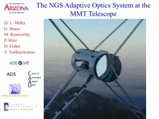
Study of an adaptive optics system for the astronomy in the visible Sandrine Thomas, A. Tokovinin, N. van der Bliek, B. Gregory, R. Tighe, R. Cantarutti, P. Schurter, E. Mondaca, D. Sprayberry Santa Cruz, 2nd of March 2006
Outline • Limitations of classical AOs • GLAO technics (Ground Layer Adaptive Optics) Description and performance • Example of SAM (SOAR Adaptive Module) TurSim, BIM60, Laser, WFS • Shack-Hartmann WFS study
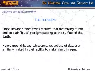
Main limitations of AO • Low sky coverage • Small isoplanetic angle (a few arcsec) • Difficult correction in the visible Nph per cm2 and per seconde Correction impossible Correction possible Wavelength in microns
Solutions • Sky coverage solution = laser guide star But: cone effect and Tip/tilt problem • Anisoplanetism solution: 3D turbulence reconstruction (tomography + MCAO) • BUT:complex system • Correction in the visible : increase of the number of actuators • BUT: complex and flux problem
GLAO • GLAO = measure and correction of the ground layer n guides stars • Tomography = measure in 3D of the turbulence • Only one star: use of the cone effet (+ measure of the tip/tilt) H h Command • Uniform correction over a larger FoV • Gain in resolution in the visible n WFSs
Why is it working?Turbulence profiles Good night 60% Bad night Tokovinin et al. 2003, campain at Cerro Pàchon
0.7 μm Seeing On-axis 1’ 2’ 3’ Performance of SAM GLAO + 1 laser guide star Wide FoV Visible • Good sky coverage • Improvement in FHWM (factor 2-5) COMPENSATION: wide FoV (ex 3’)
SAM and my contributions TurSim DM OAPs WFS Tokovinin A. et al, SPIE, 2004
Optical design Total transmission = 0.85-0.9 at = [0.4-0.9]m TurSim
/d PSF /r0 TurSim Physical simulation of the atmospherical turbulence • Different atmospherical conditions possible • Different speeds • Different sources: Diode laser, LED UV, LED white • r0 300 m • at 633 nm • Adjustable beam diameter d/r0<45
TurSim noise r0 Optical transfert function Zernike decomposition Thomas S., SPIE, 2004
Choice of the DM • Tests of the electrostatic mirror OKO79 from OKOTECH then of the bimorph miroir BIM60 from CILAS: • Stroke and inter-actuators stroke • Aberrations • Influence functions …. Simulated BIM60 Measured Tokovinin A., Thomas S., Vdovin G., SPIE, 2004
SAM’s DM • Pupil = 60 mm but 50 mm used • 60 actuarors • Radius of curvature =16.2 m • Astigmatism = 3 m
DM TurSim Reference WFS module CCD SAM’s prototype
Closed-loop • Image quality after correction of the mirror aberrations 20 nm rms DM corrected DM uncorrected Turbulence characteristics Closed-loop study
Starfire Optical Range (SOR) Albuquerque, NM Laser • Laser: • Nd:YAG 355nm triple, 8W at 10 kHz • LLT: D = 30cm, behind secondary, H=10km • Gating: KD*P Pockels cell, dH=150m • Tip/tilt Measurement: 2 NGS (R<18) • Quad cell • APDs connected to fiber optics Why UV? High Rayleigh diffusion (-4) Easy separation between science and WFS No visual hazard
The SHWFS (in collaboration mainly with T. Fusco, A. Tokovinin) Distorted wavefront Good precision of the position measurement Good reconstruction of the distorted wavefront Detector CCD camera Micro-lens array Spot position Reference position 2err = (Cmes – Ctrue)2 1000 iter
Atmosphere + photon and readout noise Front d’onde plan Atmosphère Parameters of the study • Spot shape • Turbulence strength r0 • Photon number per subaperture: Nph • Readout noise: Nr • Subaperture FoV • Spatial resolution:Nyquist, Nyquist/2 Context Nph= 200 Nsamp= 2 D/r0= 2 Nr= 3 Monte-Carlo simulation
Non-linearity Cmes Ctrue Centroid calculation methods • CoG: • Thresholding, T • Windowing, W • Weighted CoG,Fw • Quad Cell • Correlation Correlation peak estimation: • CoG + thresholding, T • Parabola fitting • Gaussian fitting
Term from atmospherical distortions Response coefficient Non-linearity term Noise terms Error variance expression 2err = (Cmes – Ctrue)2 1000 iter
Noise terms Ns= pixels number Nt= spot FWHM Nsamp= Sampling = correlation function FWHM W = FoV Hyp: Nyquist, Gaussian spot Hyp: Nyquist, diffraction spot • CoG WCoG (corrected by ) Correlation Paper: Thomas et al. submitted
For 4Q Term from atmospherical distortions Atmospherical turbulence only For CoG -correlation (W)
W optimization Weak turbulence Photon noise and atmospherical turbulence (W)
Methods comparison By adapting the parameters for each method, it is possible to find the minimum error with the minimum of changes
Example 1: Planet Finder Nyquist, Nr= 0.5 e-, d/r0=1 • WCoG-Correlation
SAM WFS • Shack-Hartmann • 10x10 sub-apertures • 8x8 pixels per subapertures • UV-Visible (100-1100 nm) • CCD-39 EEV + controler SDSU-III • Readout noise = 5.9e- at 200 Hz • Binning capacity (1x1, 2x2, 4x4)
Example 2: SAM Nyquist/2, Nr = 5 e-, d/r0=2 • QC then WCoG-correlation
Conclusions 1 • Adaptive optics wide FoV in the visible • Study of the main components of SAM • TurSim: Development et validation • MD: Validation and test of 2 types of mirror • Contribution to the optical design • Development and use of a prototype • Theoretical study and simulation of a SH WFS: • Definition of an error budget • Comparison of different methods of spot position • Development of analytical expressions • Application to different type of systems
Search for tertiary companions to close spectroscopic binaries In collaboration with A. Tokovinin, M. Sterzik, S. Udry VLT4 HIP 48215 Tokovinin A., Thomas S., Sterzik M., Udry S., A&A, 2006
Molecular cloud Accretion Close binaries How? Angular momentum Context How do we explain the separation of close binaries of a few days?
? q1, P1~10d q3, P3~104 yr a = demi grand-axe q = rapport des masses P = période Question: Are tertiaries needed in the SBs formation? Are all SBs part of a multiple system? Loi de Kepler’s : Eggleton 2001, Kiseleva-Eggleton,2004 Close binaries formation • Idea:orbital shrinkage • Magnetic breaking or disk breaking… • Evolution like Kozai cycle (Kozai 1962) Hypothesis: deposition of the angular momentum in a tertiary component Existence = Melo et al. 2001, Simulations: Sterzik et al. 2003
Tertiary detection Sample Technics • Close < 100pc (Hipparcos) larger separations • Periods [1j – 30j] • CORALIE, Batten et al. (1989), recent paper • Dwarfs from 0.4 to 1.7 M. ( more numerous, close, not too bright and sharp lines.) HIP 2790 30pc, G8V 165 SBs in 161 systems
NACO: AO on Yepun (VLT4) • NACO: Imagery, polarimetry, spectroscopy, coronography • = 1-5 m. • R ~ 50% in K band with a reference star of V=12 • 2 runs: Novembre 2004 and July 2005 • Band K + bands J H for some of Nov. • 72 objects observed + 2 calibrators 1pixel = 13.30 mas
Example of companions 1 = 3.70” 1 = 340 K = 2.25 HIP 98578 B 2 = 0.39” 2 = 353 K = 0.62 C A = SB Representative narrow-band images FoV = 2’’ x 2’’
Data reduction • Regular data reduction, package Eclipse • DAOPHOT procedure: fitting of the image with the primary. • PSF extraction • Position error = 0.5 mas if m<3m and 5 mas if m=5m • rms magnitude difference error = 0.02m if m<3m and 0.05m if m=5m
Detection limit • 3 detection from I (r,) • Check with simulation • Model m Separation in arcsec
False detections = 0.1”, m = 3 HIP86289
Search for wider companions 2MASS 1. Extract data, <2’ 2. Plot CMD (J, J-K) 3. Select candidates < 0.2m from the main sequence • POSS: Palomar Observatory Sky Survey N* = 8 2 physical companions
MSC catalog(Tokovinin,1997) Our observations Tertiaries Binaries P3=104 P1 P3= 5 P1 Period distribution N Period P1, d SBs with a tertiaires have a significatively larger fraction of systems with P1<10d
Probability q3 logP3 Correction for incomplete detection • Correction done by maximum likelyhood
Fraction of tertiary vs SB’s period 96% of SBs with P<3d have tertiaries Less SBs have tertiaries Robust method
Conclusions 2 • Tertiary fraction depends on the period P1 of the SBs • For P1<3d, almost all SBs multiple systems • If P1 is bigger, pure SBs. Tertiary frequency < one of solar type systems • Different period distribution between triple and binaries • Same mass distribution • No relation between P1 and P3 • Most massive component = closest one pure SBs no Kozai cycle Hyp: accretion, disk braking. SBs could have lost their tertiaries.
Perspectives • Implementation of GLAO systems • 1st generation of AO for the ELTs • Follow-up of the WFS study in the case of a laser guide star • Problem of SBs is only partially resolved • Other science: Brown dwarf formation, Herbig AeBe star formation.