Download
1 / 40
410 likes | 632 Views
Regression & Deconvolution. Presented by Keith McGregor. Slides courtesy of Bob Cox, PhD @ NIH. DECONVOLUTION…but first…. Signal = Measurable response to stimulus Noise = Components of measurement that interfere with detection of signal Signal detection theory:

E N D
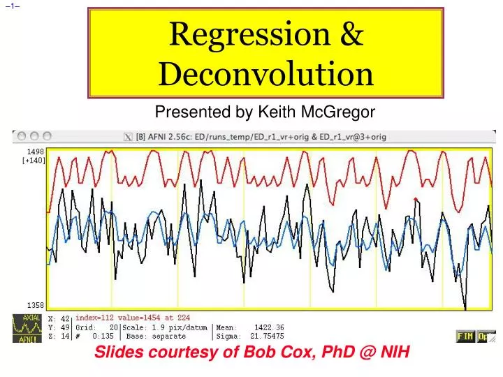
Regression & Deconvolution Presented by Keith McGregor Slides courtesy of Bob Cox, PhD @ NIH
DECONVOLUTION…but first… • Signal = Measurable response to stimulus • Noise = Components of measurement that interfere with detection of signal • Signal detection theory: • Understand relationship between stimulus & signal • Characterize noise statistically • Can then devise methods to distinguish noise-only measurements from signal+noise measurements, and assess their reliability • Methods and usefulness depend strongly on the assumptions
FMRI Philosopy: Signals and Noise • FMRI Stimulus--Signal connection and noise statistics are both poorly characterized • “SNR’s are like a box of chocolates…” • Result: there is no “best” way to analyze FMRI time series data: there are only “reasonable” analysis methods • Assumptions have to be made to deal with data • Different kinds of experiments require different kinds of analyses • Different Questions = Different Signal • It is important to understand what is going on, so you can select and evaluate “reasonable” analyses • MODEL SIGNAL & NOISE MATHEMATICALLY
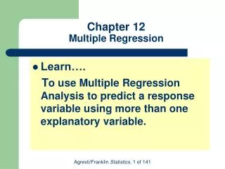
Time Series Analysis on Voxel Data • Most common forms of FMRI analysis involve fitting an activation+BOLD model to each voxel’s time series separately (AKA “univariate” analysis) • Some pre-processing steps may do inter-voxel computations (e.g., spatial smoothing) • Result of model fits is a set of parameters at each voxel, estimated from that voxel’s data • e.g., activation amplitude, delay, shape • “SPM” = statistical parametric map • Further analysis steps operate on individual SPMs • e.g., combining/contrasting data among subjects
Sample FMRI Data Time Series • Event-related FMRI • “Activation” occurs in single relatively brief intervals • “Events” can be randomly or regularly spaced in time • If events are randomly spaced in time (“Jittered”), signal model itself looks noise-like • ER designs: BOLD response to stimulus tends to be weaker since fewer nearby-in-time “activations” have overlapping hemodynamic responses • “Strength in numbers” idea
Two Voxel Time Series from Same Run correlation with ideal = 0.56 correlation with ideal = –0.01 ER-FMRI activation is not obvious via casual inspection
Hemodynamic Response Function (HRF) • HRF is the idealization of measurable FMRI signal change responding to a single activation cycle (up and down) from a stimulus in a voxel • Response to brief activation (< 1 s): • delay of 1-2 s • rise time of 4-5 s • fall time of 4-6 s • model equation: • h(t) is signal change tseconds after activation 1 Brief Activation
Linearity of HRF • Multiple activation cycles in a voxel, closer in time than duration of HRF: • !Assume:! Overlapping responses add ASSUMPTION: • Linearity is a fair (~90% accuracy) assumption (Buckner & Dale, 1997) • Widely taken to be true and is the basis for the “general linear model” (GLM) in FMRI 3 Brief Activations
Convolution Signal Model • FMRI signal we look for in each voxel is taken to be sum of the individual trial HRFs • Stimulus timing is assumed known (or measured) • Resulting time series (blue curves) are called the convolution of the HRF with the stimulus timing • Must also allow for baseline and baseline drifting • Convolution models only the FMRI signal changes 22 s 120 s • Real data starts at and • returns to a nonzero, • slowly drifting baseline
Simple Regression Models • Assume a fixed shape h(t) for the HRF • e.g., h(t) = t8.6 exp(-t/0.547) [MS Cohen, 1997] • Convolved with stimulus timing (e.g., AFNI program waver), get ideal response function r(t) • Assume a form for the baseline • e.g., a + bt for a constant plus a linear trend • In each voxel, fit data Z(t) to a curve of the form Z(t) a + bt + r(t) • a, b, are unknown parameters to be calculated in each voxel • a,b are “nuisance” parameters • is amplitude of r(t) in data = “how much” BOLD
Simple Regression: Example Constant baseline: a Quadratic baseline: a+bt+ct2 • Necessary baseline model complexity depends on duration of continuous imaging — e.g., 1 parameter per 100 seconds
Multiple Stimuli = Multiple Regressors • Usually have more than one class of stimulus or activation in an experiment • e.g., want to see size of “face activation” vis-à-vis “house activation”; or, “what” vs. “where” activity • Need to model each separate class of stimulus with a separate response function r1(t ),r2(t ), r3(t ), …. • Each rj(t ) is based on the stimulus timing for activity in class number j • Calculate a j amplitude = amount of rj(t ) in voxel data time seriesZ(t ) • Contrast s to see which voxels have differential activation levels under different stimulus conditions • e.g., statistical test on the question 1–2 = 0 ?
Equations: Multiple Response Functions • In each voxel, fit data Zn to a curve of the form • j is amplitude in data of rn(j)=rj(tn) ; i.e., “how much” of jth response function in in the data time series • In simple regression, each rj(t) is derived directly from stimulus timing anduser-chosen HRF model • In terms of stimulus times: • If stimulus occurs on the imaging TR time-grid, stimulus can be represented as a 0-1 time series: 000000010000000100000000000100000000000010 Stimulus
Multiple Regressors & Collinearity • Green curve = signal model for #1 • Red curve = signal model for class #2 • Blue curve = signal model for #3 • Purple curve = #1+#2+#3 which is exactly = 1 • We cannot — in principle or in practice— distinguish sum of 3 signal models from constant baseline!! No analysis can distinguish the cases Z(t)=10+ 5#1 and Z(t)= 0+15#1+10#2+10#3 and an infinity of other possibilities Collinear designs BAD
Simple Regression: Summary • Choose HRF model h(t) [a.k.a.- fixed-model regression] • Build model responses rn(t)to each stimulus class • Using h(t) and the stimulus timing • Choose baseline model time series • Constant + linear + quadratic + movement? • Assemble model and baseline time series into the columns of the R matrix • For each voxel time series z, solve zRfor • Individual subject maps: Test the coefficients in that you care about for statistical significance • Group maps: Transform the coefficients in that you care about to Talairach space, and perform statistics on these values
Deconvolution • Simple or Fixed-shape regression • We fixed the shape of the HRF • Used waver to generate the signal model from the stimulus timing • Found the amplitude of the signal model in each voxel • Deconvolution or Variable-shape regression • We allow the shape of the HRF to vary in each voxel, for each stimulus class • Appropriate when you don’t want to over-constrain the solution by assuming an HRF shape • However, need to have enough time points during the HRF in order to resolve its shape
Deconvolution: Pros and Cons • Letting HRF shape varies allows for subject and regional variability in hemodynamics • Can test HRF estimate for different shapes; e.g., are later time points more “active” than earlier? • Need to estimate more parameters for each stimulus class than a fixed-shape model (e.g., 4-15 vs. 1) • Need more data to get the same statistical power (assuming that the fixed-shape model you would assume was in fact “correct”) • Freedom to get any shape in HRF results can give weird shapes that are difficult to interpret – TRUST ME…
Expressing HRF via Regression Unknowns • The tool for expressing an unknown function as a finite set of numbers that can be fit via linear regression is an expansion in basis functions • The basis functions q(t) are known, as is the expansion order p • The unknowns to be found (in each voxel) comprises the set of weightsqfor each q(t) • Since weights appear only by multiplying known values, and HRF only appears by in final signal model by linear convolution, resulting signal model is still solvable by linear regression
Basis Function: “Sticks” • The set of basis functions you use determines the range of possible HRFs that you can compute • “Stick” (or Dirac delta) functions are very flexible • But they come with a strict limitation – • h(t) = 0 for any t not on the TR grid • Deconvolution Interval limiting (p) • (t) is 1 at t=0 and is 0 at all other values of t • q(t) = (t–qTR) for q=0,1,2,…,p • h(0) = 0 • h(TR) = 1 • h(2 TR) = 2 • h(3 TR) = 3 • et cetera • h(t) = 0 for any t not on the TR grid Each piece of h(t) looks like a stick poking up h time t=2TR t=3TR t=4TR t=5TR t=0 t=TR
Sticks: Good Points • Can represent arbitrary shapes of the HRF, up and down, with ease -- (Dirac Delta) • Meaning of each qis completely obvious • Value of HRF at time lag qTR after activation • 3dDeconvolve is set up to deal with stick functions for representing HRF, so using them is very easy • What is called p here is given by command line option -stim_maxlag in the program • When choosing p, rule is to estimate longest duration of neural activation after stimulus onset, then add 10-12 seconds to allow for slowness of hemodynamic response
Sticks and TR-locked Stimuli • h(t) = 0 for any t not on the TR grid • This limitation means that, using stick functions as our basis set, we can only model stimuli that are “locked” to the TR grid • That is, stimuli/activations don’t occur at fully general times, but only occur at integer multiples of TR • For example, suppose an activation is at t=1.7TR • We need to model the response at later times, such as 2TR, 3TR, etc., so need to model h(t) at times such as t=0.3TR, 1.3TR, etc., after the stimulus • Stick function model doesn’t allow for such intermediate times
Deconvolution with Stick Functions • Instead of inputting a signal model time series you input the stimulus timing directly • Format: a text file (.1D) with 0s and 1s, 0 at TR-grid times with no stimulus, 1 at time with stimulus • Must specify the maximum lag (in units of TR) that we expect HRF to last after each stimulus • This requires you to make a judgment about the activation — brief or long? IMPORTANT!!!!!!!!! • 3dDeconvolve returns estimated values for each q for each stimulus class • Usually then use a GLT to test the HRF (or pieces of it) for significance (R2 or F-test)
h3 h2 h4 h1 h5 h7 h0 h6 TR (t) S(t) : 010010000001000000000 I(t)task = ΣHDRs I(0)task = S(t)* h0 = 0* h0 = 0 I(1)task = S(t-1)* h1+ S(t)* h0 = 0+h0 I(2)task = S(t-2)* h2+ S(t-1)* h1+ S(t)* h0 = 0+ h1+0 I(3)task = S(t-3)* h3+ S(t-2)* h2+ S(t-1)* h1+ S(t)* h0 = 0+h2+0+0 I(4)task = S(t-4)* h4+ S(t-3)*h3+ S(t-2)*h2+ S(t-1)*h1+ S(t)*h0 = 0+h3+0+0+h0 I(5)task = S(t-5)* h5+ S(t-4)* h4+ S(t-3)*h3+ S(t-2)* h2+ S(t-1)* h1+ S(t)* h0= 0+h4+0+0+h1+0
0 +4 0 +4 0 +4 1 +5 1 +5 1 +5 3 3 3 2 2 2 Equations at each time point: Cannot tell 0 from 4, or 1 from 5 0 1 2 3 HRF from stim #1 0 0 0 1 1 1 2 2 2 3 3 3 4 4 4 5 5 5 stim #1 Deconvolution and Collinearity • Regular stimulus timing can lead to collinearity! time stim #4 stim #2 stim #3
Results: Humans vs. Tools • Color overlay is HvsT contrast • Blue curves are Human HRFs • Red & Green curves are Tool HRFs
Glover (1999) • Voxel specific hemodynamic response function (HRF) has been found to be variable across: • Brain Areas: V1 vs. Motor (Boynton et al., 1996) • Nonlinear in V1 (Vazquez et al, 1998) • Previously accounted for non-linearity via fixed HRF (Friston, 1996) & requires GLM approach w/o variation • Subjects (Aguirre et al, 1998) • Sensorimotor activity • Use of Deconvolution to measure HRF in: • Multiple Cortices • Multiple Subjects • Multiple Stimuli Patterns • Potential challenge to Linearity Assumption & Balloon model (Buxton et al., 1998)
Method • EXPERIMENT 1 (Block) • Auditory cued tapping task at variable tapping rates • Every 30 seconds for 10 trials a 3Hz tone played over earphones in scanner • Subjects tapped bilaterally @ varying duration • EXPERIMENT 2A (ER - RANDOM) • Spacing of events (tapping) were set to OVERLAP as to provide an additive signal (Convolved regressors ) • Job of Deconvolution is to extract signal variance due to individual stimulus regressors • Assumption of independence here SLIGHTLY VIOLATED: COLLINEARITY NOT IMPOSSIBLE • EXPERIMENT 2B • Replicated 2A but added tapping frequency variation to generate discrete HRF’s for each frequency • Designed to test the LINEARITY of deconvolution with overlapping responses at different levels of activation (multiple regressors)
Analysis • Standard Correlational analysis with fixed HRF’s against deconvolution were used • Deconvolution accounted for variance that correlational data could not in extracting signal properties
Decon Decon
Decon Decon
Multiple Regressors: Cartoon • Red curve = signal model for class #1 • Green curve = signal model for #2 • Blue curve = 1#1+2#2 where 1 and 2 vary from 0.1 to 1.7 in the animation • Goal of regression is to find 1 and 2 that make the blue curve best fit the data time series • Gray curve = 1.5#1+0.6#2+noise = simulated data
Multiple Regressors: Near Collinearity • Red curve = signal model for class #1 • Green curve = signal model for #2 • Blue curve = 1#1+(1–1)#2 where 1varies randomly from 0.0 to 1.0 in animation • Gray curve = 0.66#1+0.33#2 = simulated data with no noise • Lots of different combinations of #1 and #2 are decent fits to gray curve Red & Green stimuli average 2 s apart Stimuli are too close in time to distinguish response #1 from #2, considering noise