Download
1 / 34
340 likes | 352 Views
ATM NETWORKS. A Comprehensive Survey .. Aditya Peri. The Past. The mid 1800’s saw the rising of the ATM technology. At that time, there were predominantly only two types of networks .. Telephone Networks which were primarily used for carrying real time voice

E N D
ATM NETWORKS A Comprehensive Survey .. Aditya Peri.
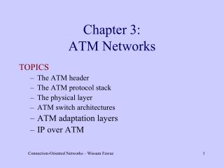
The Past.. • The mid 1800’s saw the rising of the ATM technology. • At that time, there were predominantly only two types of networks .. • Telephone Networks which were primarily used for carrying real time voice • Data Networks which was primarily used to carry text files , support remote login , and provide email. • Thus there was a urgent need for an integrated networking medium , which could implement the functionalities of both the telephone and the data networks. Thus , the Asynchronous Transfer Mode was born. • Two committees namely , the ATM forum [ ATM 2002] and the International Telecommunication Union [ ITU 2002]
Contd… developed standards for broadband digital services networks. • The ATM standards call for packet switching with virtual circuits ( called virtual channels in ATM jargons ) • The Standards define how applications directly interface with ATM , so that ATM provides a complete networking solution for distributed application • Paralleling the development of ATM standards , major companies started investing heavily in ATM Research and Development. • This led to a myriad of high performing ATM technologies including ATM switches, that can switch terabits / sec.
How ATM was born ? • ATM was developed because of developing trends in the networking field. • The most important parameter is the emergence of a large number of communication services with different, sometimes yet unknown requirements. • In this information age, customers are requesting an ever increasing number of new services. • The most demanding communication services to take over in the future are, video conferencing, high speed data transfer, video phony, video library, home education and video on demand. • Two other parameters are the fast evolution of the semi - conductor and optical technology and the evolution in system concept ideas - the shift of superfluous transport functions to the edge of the network
What's going wrong ? • Both the need for a flexible network and the progress in technology and system concepts led to the definition of the Asynchronous Transfer Mode (ATM) principle • Although ATM has been deployed within networks , its been less successful in extending itself all the way to desktop PC’s and workstations. • And its Now questionable whether ATM will ever have a significant presence at the desktop indeed
The TCP/IP Intrusion … • The Early 90’s saw the advent of the TCP/IP , which already were operational and making a significant headway. • The TCP/IP suite was integrated into all of the most popular operating systems. • Companies began to transact commerce ( e -commerce ) over the internet. • Residential Internet became inexpensive.. • Many wonderful desktop applications were developed for TCP/IP networks, including the www , internet phone , interactive streaming video…etc.
ATM Characteristics…. • The ATM Standard defines a full suite of communication protocols , from an application level API all the way down through the physical layer. • The ATM service Models include constant bit rate ( CBR ) service , variable bit rate ( VBR ) service , and unspecified bit rate ( UBR ) . • The ATM uses packet switching with fixed length packets of 53 bytes . In the ATM jargon these packets are called CELLS. Each cell had five bytes of header and 48 bytes of “ Payload ”. The fixed length cells and headers facilitate high speed switching. • ATM uses Virtual circuits , called Virtual channels in ATM Jargon, The ATM header includes a field for virtual channel number called Virtual channel Identifier ( VCI).
The packet Switches use the VCI to forward their cells to their destinations. • The ATM provides no retransmissions on a link by link basis. If a switch detects an error in an ATM cell header , it attempts to correct the error using the error correcting codes. If it cannot correct the error , it drops the cell rather than request a retransmission from the preceeding switch. • ATM provides Congestion control only within the ATM ABR service Class ( Belongs to the General Class of network assisted congestion control approaches ) . • ATM can run over just about any physical layer. It often runs over fiber optics using the SONET standard at speeds of 155.52 Mbps, 622Mbps and Higher…
Asynchronous Transfer Mode Switching • Figure 1- A Private ATM Network and a Public ATM Network Both Can Carry Voice, Video, and Data Traffic
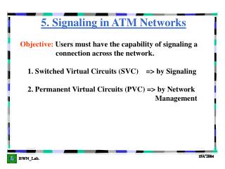
Standards… • ATM is based on the efforts of the ITU-T Broadband Integrated Services Digital Network (B-ISDN) standard. It was originally conceived as a high-speed transfer technology for voice, video, and data over public networks. The ATM Forum extended the ITU-T's vision of ATM for use over public and private networks. The ATM Forum has released work on the following specifications: • User-to-Network Interface (UNI) 2.0 • UNI 3.0 • UNI 3.1 • UNI 4.0 • Public-Network Node Interface (P-NNI) • LAN Emulation (LANE) • Multi protocol over ATM
ATM Devices and the Network Environment • ATM is a cell-switching and multiplexing technology that combines the benefits of circuit switching (guaranteed capacity and constant transmission delay) with those of packet switching (flexibility and efficiency for intermittent traffic). It provides scalable bandwidth from a few megabits per second (Mbps) to many gigabits per second (Gbps). Because of its asynchronous nature, ATM is more efficient than synchronous technologies, such as time-division multiplexing (TDM). • With TDM, each user is assigned to a time slot, and no other station can send in that time slot. If a station has much data to send, it can send only when its time slot comes up, even if all other time slots are empty. However, if a station has nothing to transmit when its time slot comes up, the time slot is sent empty and is wasted. Because ATM is asynchronous, time slots are available on demand with information identifying the source of the transmission contained in the header of each ATM cell.
ATM Cell Basic Format • ATM transfers information in fixed-size units called cells. Each cell consists of 53 octets, or bytes. The first 5 bytes contain cell-header information, and the remaining 48 contain the payload (user information). Small, fixed-length cells are well suited to transferring voice and video traffic because such traffic is intolerant of delays that result from having to wait for a large data packet to download, among other things. • Figure 2 - An ATM Cell Consists of a Header and Payload Data
Header Format Table 1 ATM cell header format (UNI)
The ATM header contains information about destination, type and priority of the cell. • The Generic Flow Control (GFC) field allows a multiplexer to control the rate of an ATM terminal. The GFC field is only available at the User-to-Network Interface (UNI). At the Network-to-Network Interface (NNI) these bits belong to the Virtual Path Identifier (VPI). • The Virtual Path Identifier (VPI) and the Virtual Channel Identifier (VCI) hold the locally valid relative address of the destination. These fields may be changed within an ATM switch. • The Payload Type (PT) marks whether the cell carries user data, signaling data or maintenance information. • The Cell Loss Priority (CLP) bit indicates which cells should be discarded first in the case of congestion. • Finally, the Header Error Control (HEC) field is to perform a CRC check on the header data. Only the header is error checked in the ATM layer. Error check for the user data is left to higher layer protocols and is performed on an end-to-end base.
ATM Devices • An ATMnetwork is made up of an ATMswitch and ATMendpoints. • An ATM switch is responsible for cell transit through an ATM network. The job of an ATM switch is well defined: It accepts the incoming cell from an ATM endpoint or another ATM switch. It then reads and updates the cell header information and quickly switches the cell to an output interface toward its destination. • An ATM endpoint (or end system) contains an ATM network interface adapter. Examples of ATM endpoints are workstations, routers, digital service units (DSUs), LAN switches, and video coder-decoders (CODECs). Figure 3 illustrates an ATM network made up of ATM switches and ATM endpoints
ATM Networks… Figure 3- An ATM Network Comprises ATM Switches and Endpoints
ATM Network Interfaces • An ATM network consists of a set of ATM switches interconnected by point-to-point ATM links or interfaces. ATM switches support two primary types of interfaces: UNI and NNI. • The UNI connects ATM end systems (such as hosts and routers) to an ATM switch. The NNI connects two ATM switches. • Depending on whether the switch is owned and located at the customer's premises or is publicly owned and operated by the telephone company, UNI and NNI can be further subdivided into public and private UNIs and NNIs. • A private UNI connects an ATM endpoint and a private ATM switch. Its public counterpart connects an ATM endpoint or private switch to a public switch. A private NNI connects two ATM switches within the same private organization. A public one connects two ATM switches within the same public organization. • An additional specification, the broadband intercarrier interface (B-ICI), connects two public switches from different service providers. Figure 4 illustrates the ATM interface specifications for private and public networks.
Figure 4 -ATM Interface Specifications Differ for Private and Public Networks
ATM Reference Model The ATM reference model is composed of the following ATM layers: • Physical layer—Analogous to the physical layer of the OSI reference model, the ATM physical layer manages the medium-dependent transmission. • ATM layer—Combined with the ATM adaptation layer, the ATM layer is roughly analogous to the data link layer of the OSI reference model. The ATM layer is responsible for the simultaneous sharing of virtual circuits over a physical link (cell multiplexing) and passing cells through the ATM network (cell relay). To do this, it uses the VPI and VCI information in the header of each ATM cell. • ATM adaptation layer (AAL)—Combined with the ATM layer, the AAL is roughly analogous to the data link layer of the OSI model. The AAL is responsible for isolating higher-layer protocols from the details of the ATM processes. The adaptation layer prepares user data for conversion into cells and segments the data into 48-byte cell payloads. • Finally, the higher layers residing above the AAL accept user data, arrange it into packets, and hand it to the AAL.
OSI against ATM.. Figure 7 - The ATM Reference Model Relates to the Lowest Two Layers of the OSI Reference Model
Plane Model.. • The ATM architecture uses a logical model to describe the functionality that it supports. ATM functionality corresponds to the physical layer and part of the data link layer of the OSI reference model. • The ATM reference model is composed of the following planes, which span all layers: • Control—This plane is responsible for generating and managing signaling requests. • User—This plane is responsible for managing the transfer of data. • Management—This plane contains two components: • Layer managementmanages layer-specific functions, such as the detection of failures and protocol problems. • Plane management manages and coordinates functions related to the complete system
The ATM Physical Layer • The ATM physical layer has four functions : • Cells are converted into a bit stream , • The transmission and receipt of bits on the physical medium are controlled , • ATM cell boundaries are tracked , • Cells are packaged into the appropriate types of frames for the physical medium. For example, cells are packaged differently for SONET than for DS-3/E-3 media types. • The ATM physical layer is divided into two parts: the physical medium-dependent (PMD) sub layer and the transmission convergence (TC) sub layer • The PMD sub layer provides two key functions : • It synchronizes transmission and reception by sending and receiving a continuous flow of bits with associated timing information . • Secondly, it specifies the physical media for the physical medium used , including connector types and cable
The ATM Adaptation Layers.. • The TC sub layer has four functions: • cell delineation • header error control (HEC) sequence generation and verification, • cell-rate decoupling , and transmission frame adaptation • The cell delineation function maintains ATM cell boundaries, allowing devices to locate cells within a stream of bits. • HEC sequence generation and verification generates and checks the header error control code to ensure valid data. • Cell-rate decoupling maintains synchronization and inserts or suppresses idle (unassigned) ATM cells to adapt the rate of valid ATM cells to the payload capacity of the transmission system. • Transmission frame adaptation packages ATM cells into frames acceptable to the particular physical layer implementation.
ATM Adaptation Layer AAL1 : • AAL1, a connection-oriented service, is suitable for handling constant bit rate sources (CBR), such as voice and videoconferencing • The AAL1 process prepares a cell for transmission in three steps. First, synchronous samples (for example, 1 byte of data at a sampling rate of 125 microseconds) are inserted into the Payload field. • Second, Sequence Number (SN) and Sequence Number Protection (SNP) fields are added to provide information that the receiving AAL1 uses to verify that it has received cells in the correct order. • Third, the remainder of the Payload field is filled with enough single bytes to equal 48 bytes .
Figure 8 - AAL1 Prepares a Cell for Transmission So That the Cells Retain Their Order SN= Sequence No , SNP = Sequence no protection
Contd…. • ATM Adaptation Layer AAL2 : • Another traffic type has timing requirements like CBR but tends to be bursty in nature. This is called variable bit rate (VBR) traffic. This typically includes services characterized as packetized voice or video that do not have a constant data transmission speed but that do have requirements similar to constant bit rate services. AAL2 is suitable for VBR traffic • ATM Adaptation Layers AAL3/4 : • AAL3/4 supports both connection-oriented and connectionless data. It was designed for network service providers and is closely aligned with Switched Multimegabit Data Service (SMDS). AAL3/4 is used to transmit SMDS packets over an ATM network.
ATM Adaptation Layer AAL5 : • AAL5 is the primary AAL for data and supports both connection-oriented and connectionless data. It is used to transfer most non-SMDS data, such as classical IP over ATM and LAN Emulation (LANE). AAL5 also is known as the simple and efficient adaptation layer (SEAL) because the SAR sub layer simply accepts the CS-PDU and segments it into 48-octet SAR-PDUs without reserving any bytes in each cell .
The ATM Connection-Establishment Process Figure 10- ATM Devices Establish Connections Through the One-Pass Method
ATM signaling uses the one-pass method of connection setup that is used in all modern telecommunication networks, such as the telephone network. An ATM connection setup proceeds in the following manner : • First , the source end system sends a connection-signaling request. The connection request is propagated through the network. As a result, connections are set up through the network. The connection request reaches the final destination, which either accepts or rejects the connection request.
ATM Connections. • ATM supports two types of connections: point-to-point and point-to-multipoint. • Point-to-point connects two ATM end systems and can be unidirectional (one-way communication) or bidirectional (two-way communication). • Point-to-multipoint connects a single-source end system (known as the root node) to multiple destination end systems (known as leaves). Such connections are unidirectional only. • Root nodes can transmit to leaves, but leaves cannot transmit to the root or to each other on the same connection. Cell replication is done within the ATM network by the ATM switches where the connection splits into two or more branches • It would be desirable in ATM networks to have bidirectional multipoint-to-multipoint connections. Such connections are analogous to the broadcasting or multicasting capabilities of shared-media LANs, such as Ethernet and Token Ring. A broadcasting capability is easy to implement in shared-media LANs, where all nodes on a single LAN segment must process all packets sent on that segment.
Contd… • Unfortunately, a multipoint-to-multipoint capability cannot be implemented by using AAL5, which is the most common AAL to transmit data across an ATM network. • Unlike AAL3/4, with its Message Identifier (MID) field, AAL5 does not provide a way within its cell format to interleave cells from different AAL5 packets on a single connection. This means that all AAL5 packets sent to a particular destination across a particular connection must be received in sequence; otherwise, the destination reassembly process will be incapable of reconstructing the packets . • This is why AAL5 point-to-multipoint connections can be only unidirectional. If a leaf node were to transmit an AAL5 packet onto the connection, for example, it would be received by both the root node and all other leaf nodes. At these nodes, the packet sent by the leaf could be interleaved with packets sent by the root and possibly other leaf nodes, precluding the reassembly of any of the interleaved packets
LAN Emulation • LAN Emulation (LANE) is a standard defined by the ATM Forum that gives to stations attached via ATM the same capabilities that they normally obtain from legacy LANs, such as Ethernet and Token Ring. As the name suggests, the function of the LANE protocol is to emulate a LAN on top of an ATM network. Specifically, the LANE protocol defines mechanisms for emulating either an IEEE 802.3 Ethernet or an 802.5 Token Ring LAN
Current / Future Research.. • Mobility Management in Wireless ATM Networks • Multiple access control protocols for wireless ATM • Design and analysis of low-power access protocols for wireless and mobile ATM networks • ATM-based routing in LEO/MEO satellite networks with inter satellite links • Rerouting for handoff in a wireless ATM network
References.. • http://www2.rad.com/networks/1994/atm/tutorial.htm • http://www.cisco.com • http://ieeexplore.ieee.org.