Download
1 / 46
460 likes | 591 Views
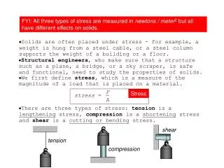
Materials. Properties Mechanics. Why we need to know about materials. Stuff is made of stuff what should your part be made of? what does it have to do? how thick should you make it The properties we usually care about are: stiffness electrical conductivity thermal conductivity

E N D
Materials Properties Mechanics
UCSD: Physics 121; 2012 Why we need to know about materials • Stuff is made of stuff • what should your part be made of? • what does it have to do? • how thick should you make it • The properties we usually care about are: • stiffness • electrical conductivity • thermal conductivity • heat capacity • coefficient of thermal expansion • density • hardness, damage potential • machine-ability • surface condition • suitability for coating, plating, etc.
UCSD: Physics 121; 2012 Electrical Resistivity • Expressed as in ·m • resistance = ·L/A • where L is length and A is area • conductivity is1/
UCSD: Physics 121; 2012 Thermal Conductivity • Expressed as in W m-1 K-1 • power transmitted = ·A·T/t, • where A is area, t is thickness, and T is the temperature across the material
UCSD: Physics 121; 2012 Specific Heat (heat capacity) • Expressed as cp in J kg-1 K-1 • energy stored = cp·m·T • where m is mass and T is the temperature change
UCSD: Physics 121; 2012 Coefficient of Thermal Expansion • Expressed as = L/L per degree K • length contraction = ·T·L, • where T is the temperature change, and L is length of material
UCSD: Physics 121; 2012 Density • Expressed as = m/V in kg·m-3
UCSD: Physics 121; 2012 Stress and Strain • Everything is a spring! • nothing is infinitely rigid • You know Hooke’s Law: F = k·L • where k is the spring constant (N/m), L is length change • for a given material, k should be proportional to A/L • say k = E·A/L, where E is some elastic constant of the material • Now divide by cross-sectional area F/A = = k·L/A = E· = E· • where is L/L: the fractional change in length • This is the stress-strain law for materials • is the stress, and has units of pressure • is the strain, and is unitless
UCSD: Physics 121; 2012 Stress and Strain, Illustrated • A bar of material, with a force F applied, will change its size by: L/L = = /E = F/AE • Strain is a very useful number, being dimensionless • Example: Standing on an aluminum rod: • E = 70109 N·m2 (Pa) • say area is 1 cm2 = 0.0001 m2 • say length is 1 m • weight is 700 N • = 7106 N/m2 • = 104 L = 100 m • compression is width of human hair L F F A L = F/A • = L/L = E·
UCSD: Physics 121; 2012 Elastic Modulus • Basically like a spring constant • for a hunk of material, k = E(A/L), but E is the only part of this that is intrinsic to the material: the rest is geometry • Units are N/m2, or a pressure (Pascals)
UCSD: Physics 121; 2012 Bending Beams • A bent beam has a stretched outer surface, a compressed inner surface, and a neutral surface somewhere between • If the neutral length is L, and neutral radius is R, then the strain at some distance, y, from the neutral surface is (R + y)/R 1 • = y/R • because arclength for same is proportional to radius • note L = R • So stress at y is = Ey/R tension: stretched neutral “plane” compression
UCSD: Physics 121; 2012 In the Moment • Since each mass/volume element is still, the net force is zero • Each unit pulls on its neighbor with same force its neighbor pulls on it, and on down the line • Thus there is no net moment (torque) on a mass element, and thus on the whole beam • otherwise it would rotate: angular momentum would change • But something is exerting the bending influence Bending Moments dV And we call this “something” the moment (balanced)
UCSD: Physics 121; 2012 What’s it take to bend it? • At each infinitesimal cross section in rod with coordinates (x, y) and area dA = dxdy: • dF = dA = (Ey/R)dA • where y measures the distance from the neutral surface • the moment (torque) at the cross section is just dM = y·dF • so dM = Ey2dA/R • integrating over cross section: • where we have defined the “moment of inertia” as
UCSD: Physics 121; 2012 Energy in the bent beam • We know the force on each volume element: • dF = ·dA = E··dA = (Ey/R)dA • We know that the length changes by L = dz = ·dz/E • So energy is: • dW = dF·L = dF··dz = E··dA ·dz = E(y/R)2dxdydz • Integrate this throughout volume • So W = M(L/R) M 2 • where is the angle through which the beam is bent z-direction
UCSD: Physics 121; 2012 Calculating beam deflection • We start by making a free-body diagram so that all forces and torques are balanced • otherwise the beam would fly/rotate off in some direction • In this case, the wall exerts forces and moments on the beam (though Ax=0) • This example has three point masses and one distributed load
UCSD: Physics 121; 2012 Tallying the forces/moments • Ax = 0; Ay = 21,000 lbs • Mext = (4)(4000) + (8)(3000) + (14)(2000) + (11)(6)(2000) = 200,000 ft-lbs • last term is integral: • where is the force per unit length (2000 lbs/ft)
UCSD: Physics 121; 2012 A Simpler Example Fy = mg = L • A cantilever beam under its own weight (or a uniform weight) • Fy and Mext have been defined above to establish force/moment balance • At any point, distance z along the beam, we can sum the moments about this point and find: • validating that we have no net moment about any point, and thus the beam will not spin up on its own! Mext = <z>z = (L/2)L = ½ L2 z-axis force per unit length = ; total force = mg = L
UCSD: Physics 121; 2012 What’s the deflection? Fy = mg = L • At any point, z, along the beam, the unsupported moment is given by: • From before, we saw that moment and radius of curvature for the beam are related: • M = EI/R • And the radius of a curve, Y, is the reciprocal of the second derivative: • d2Y/dz2 = 1/R = M/EI • so for this beam, d2Y/dz2 = M/EI = Mext = <z>z = (L/2)L = ½ L2 z-axis force per unit length = ; total force = mg = L
UCSD: Physics 121; 2012 Calculating the curve • If we want to know the deflection, Y, as a function of distance, z, along the beam, and have the second derivative… • Integrate the second derivative twice: • where C and D are constants of integration • at z=0, we define Y=0, and note the slope is zero, so C and D are likewise zero • so, the beam follows: • with maximum deflection at end:
UCSD: Physics 121; 2012 Bending Curve, Illustrated • Plastic ruler follows expected cantilever curve!
UCSD: Physics 121; 2012 End-loaded cantilever beam Fy = F • Playing the same game as before (integrate moment from z to L): • which integrates to: • and at z=0, Y=0 and slope=0 C = D = 0, yielding: Mext = FL F
UCSD: Physics 121; 2012 Simply-supported beam under own weight Fy = mg/2 = L/2 Fy = mg/2 = L/2 • This support cannot exert a moment • at z=0, Y=0 D = 0; at z=L/2, slope = 0 C = L3/12 force per unit length = ; total force = mg = L
UCSD: Physics 121; 2012 Simply-supported beam with centered weight Fy = F/2 Fy = F/2 • Working only from 0 < z < L/2 (symmetric): • integrating twice, setting Y(0) = 0, Y’(L/2) = 0: • and the max deflection (at z=L/2): F
UCSD: Physics 121; 2012 S-flex beam F “walls” are held vertical; beam flexes in “S” shape total M(z) = 2Mext Fz F(Lz) = 0 for all z • Playing the same game as before (integrate moment from z to L): • which integrates to: • and at z=0, Y=0 and slope=0 C = D = 0, yielding: Mext = FL/2 Mext = FL/2 F as it should be
UCSD: Physics 121; 2012 Cantilevered beam formulae
UCSD: Physics 121; 2012 Simply Supported beam formulae
UCSD: Physics 121; 2012 Lessons to be learned • All deflections inversely proportional to E • the stiffer the spring, the less it bends • All deflections inversely proportional to I • cross-sectional geometry counts • All deflections proportional to applied force/weight • in linear regime: Hooke’s law • All deflections proportional to length cubed • pay the price for going long! • beware that if beam under own weight, mg L also (so L4) • Numerical prefactors of maximum deflection, Ymax, for same load/length were: • 1/3 for end-loaded cantilever • 1/8 for uniformly loaded cantilever • 1/48 for center-loaded simple beam • 5/384 ~ 1/77 for uniformly loaded simple beam • Thus support at both ends helps: cantilevers suffer
UCSD: Physics 121; 2012 Getting a feel for the I-thingy • The “moment of inertia,” or second moment came into play in every calculation • Calculating this for a variety of simple cross sections: • Rectangular beam: • note the cube-power on b: twice as thick (in the direction of bending) is 8-times better! • For fixed area, win by fraction b/a b a
UCSD: Physics 121; 2012 Moments Later • Circular beam • work in polar coordinates, with y = rsin • note that the area-squared fraction (1/4) is very close to that for a square beam (1/12 when a = b) • so for the same area, a circular cross section performs almost as well as a square • Circular tube radius, R inner radius R1, outer radius R2 or, outer radius R, thickness t
UCSD: Physics 121; 2012 And more moments • Circular tube, continued • if R2 = R, R1 = Rt, for small t: I (A2/4)(R/t) • for same area, thinner wall stronger (until crumples/dents compromised integrity) • Rectangular Tube • wall thickness = t • and if t is small compared to a & b: • note that for a = b (square), side walls only contribute 1/4 of the total moment of inertia: best to have more mass at larger y-value: this is what makes the integral bigger! a b and for a square geom.:
UCSD: Physics 121; 2012 The final moment • The I-beam • we will ignore the minor contribution from the “web” connecting the two flanges • note this is just the rectangular tube result without the side wall. If you want to put a web member in, it will add an extra b3t/12, roughly • in terms of area = 2at: • The I-beam puts as much material at high y-value as it can, where it maximally contributes to the beam stiffness • the web just serves to hold these flanges apart a b
UCSD: Physics 121; 2012 Lessons on moments • Thickness in the direction of bending helps to the third power • always orient a 24 with the “4” side in the bending direction • For their weight/area, tubes do better by putting material at high y-values • I-beams maximize the moment for the same reason • For square geometries, equal material area, and a thickness 1/20 of width (where appropriate), we get: • square solid: IA2/12 0.083A2 • circular solid: IA2/4 0.080A2 • square tube: I20A2/24 0.83A2 • circular tube: I10A2/4 0.80A2 • I-beam: I20A2/8 2.5A2 • I-beam wins hands-down 10 better than solid form func. of assumed 1/20 ratio
UCSD: Physics 121; 2012 Beyond Elasticity • Materials remain elastic for a while • returning to exact previous shape • But ultimately plastic (permanent) deformation sets in • and without a great deal of extra effort
UCSD: Physics 121; 2012 Breaking Stuff • Once out of the elastic region, permanent damage results • thus one wants to stay below the yield stress • yield strain = yield stress / elastic modulus * ultimate stress quoted (see next slide for reason)
UCSD: Physics 121; 2012 Notes on Yield Stress • The entries in red in the previous table represent ultimate stress rather than yield stress • these are materials that are brittle, experiencing no plastic deformation, or plastics, which do not have a well-defined elastic-to-plastic transition • There is much variability depending on alloys • the yield stress for steels are • stainless: 280–700 • machine: 340–700 • high strength: 340–1000 • tool: 520 • spring: 400–1600 (want these to be elastic as long as possible) • aluminum alloys • 6061-T6: 270 (most commonly used in machine shops) • 7075-T6: 480
UCSD: Physics 121; 2012 Shear Stress wall dA • = G • is the shear stress (N·m-2) = force over area = F/dA • dA is now the shear plane (see diagram) • G is the shear modulus (N·m-2) • is the angular deflection (radians) • The shear modulus is related to E, the elastic modulus • E/G = 2(1+) • is called Poisson’s ratio, and is typically around 0.27–0.33 bolt F = F/A, where A is bolt’s cross-sectional area hanging mass huge force, F
UCSD: Physics 121; 2012 Practical applications of stress/strain • Infrared spectrograph bending (flexure) • dewar whose inner shield is an aluminum tube 1/8 inch (3.2 mm) thick, 5 inch (127 mm) radius, and 1.5 m long • weight is 100 Newtons • loaded with optics throughout, so assume (extra) weight is 20 kg 200 Newtons • If gravity loads sideways (when telescope is near horizon), what is maximum deflection, and what is maximum angle? • calculate I (A2/4)(R/t) = 210-5 m4 • E = 70109 • Ymax = mgL3/8EI = 90 m deflection • Y’max = mgL2/6EI = 80 R angle • Now the effect of these can be assessed in connection with the optical performance
UCSD: Physics 121; 2012 Applications, continued • A stainless steel flexure to permit parallel displacement • each flexing member has length L = 13 mm, width a = 25 mm, and bending thickness b = 2.5 mm, separated by d = 150 mm • how much range of motion do we have? • stress greatest on skin (max tension/compression) • Max strain is = y/E = 280 MPa / 200 GPa = 0.0014 • strain is y/R, so b/2R = 0.0014 R = b/0.0028 = 0.9 m • = L/R = 0.013/0.9 = 0.014 radians (about a degree) • so max displacement is about d· = 2.1 mm • energy in bent member is EIL/R2 = 0.1 J per member 0.2 J total • W = F·d F = (0.2 J)/(0.002 m) = 100 N (~ 20 lb) d
UCSD: Physics 121; 2012 Flexure Design • Sometimes you need a design capable of flexing a certain amount without breaking, but want the thing to be as stiff as possible under this deflection • strategy: • work out deflection formula; • decide where maximum stress is (where moment, and therefore curvature, is greatest); • work out formula for maximum stress; • combine to get stress as function of displacement • invert to get geometry of beam as function of tolerable stress • example: end-loaded cantilever y is displacement from centerline (half-thickness)
UCSD: Physics 121; 2012 Flexure Design, cont. • Note that the ratio F/I appears in both the Ymax and max formulae (can therefore eliminate) • If I can tolerate some fraction of the yield stress max = y/, where is the safety factor (often chosen to be 2) • so now we have the necessary (maximum) beam thickness that can tolerate a displacement Ymax without exceeding the safety factor, • You will need to go through a similar procedure to work out the thickness of a flexure that follows the S-bend type (prevalent in the Lab 2) where h = 2Δy is beam thickness
UCSD: Physics 121; 2012 Notes on Bent Member Flexure Design • When the flex members have moments at both ends, they curve into more-or-less an arc of constant radius, accomplishing angle • R = EI/M, and = L/R = ML/EI, where L is the length of the flexing beam (not the whole assembly) • max = Emax = Ey/R = hE/2L, so h = (y/E)(2L/) • where h = 2y and R = L/
UCSD: Physics 121; 2012 Kinematic Design • Physicists care where things are • position and orientation of optics, detectors, etc. can really matter • Much of the effort in the machine shop boils down to holding things where they need to be • and often allowing controlled adjustment around the nominal position • Any rigid object has 6 degrees of freedom • three translational motions in 3-D space • three “Euler” angles of rotation • take the earth: need to know two coordinates in sky to which polar axis points, plus one rotation angle (time dependent) around this axis to nail its orientation • Kinematic design seeks to provide minimal/critical constraint
UCSD: Physics 121; 2012 Basic Principles • A three-legged stool will never rock • as opposed to 4-legged • each leg removes one degree of freedom, leaving 3 • can move in two dimensions on planar floor, and can rotate about vertical axis • A pin & hole constrain two translational degrees of freedom • A second pin constrains rotation • though best if it’s a diamond-shaped-pin, so that the device is not over-constrained cut/grinding lines dowel pin a diamond pin is a home-made modification to a dowel pin: sides are removed so that the pin effectively is a one-dim. constraint rather than 2-d
UCSD: Physics 121; 2012 Diamond Pin Idea part with holes part with holes part with holes dowel pin two dowel pins wrong separation diamond pin thermal stress, machining error perfect (lucky) fit does not fit constrains only rotation but over-constrained diamond pin must be ground on grinder from dowel pin: cannot buy
UCSD: Physics 121; 2012 Kinematic Summary • Combining these techniques, a part that must be located precisely will: • sit on three legs or pads • be constrained within the plane by a dowel pin and a diamond pin • Reflective optics will often sit on three pads • when making the baseplate, can leave three bumps in appropriate places • only have to be 0.010 high or so • use delrin-tipped (plastic) spring plungers to gently push mirror against pads
UCSD: Physics 121; 2012 References and Assignment • For more on mechanics: • Mechanics of Materials, by Gere and Timoshenko • For a boatload of stress/strain/deflection examples worked out: • Roark’s Formulas for Stress and Strain • Reading from text: • Section 1.5; 1.5.1 & 1.5.5; 1.6, 1.6.1, 1.6.5, 1.6.6 (3rd ed.) • Section 1.2.3; 1.6.1; 1.7 (1.7.1, 1.7.5, 1.7.6) (4th ed.) • Additional reading on Phys239 website from 2010 • http://www.physics.ucsd.edu/~tmurphy/phys239/lectures/twm_lecture6.pdf • very similar development to this lecture, with more text