Download
1 / 8
110 likes | 204 Views
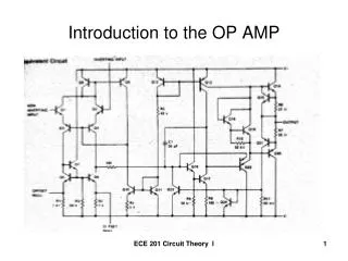
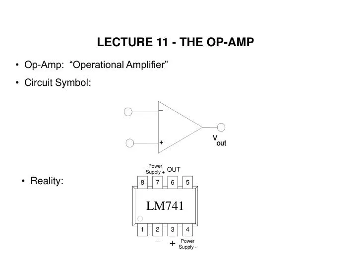
LECTURE 11 - THE OP-AMP. Op-Amp: “Operational Amplifier” Circuit Symbol:. Reality:. Differential Amplifier. Circuit Model in linear region. V 0. V +. +. A. AV 1. R i. . V . +. . +. +. V 1. V 0. But if A ~ , is the output infinite?. “Very high gain” . . .

E N D
LECTURE 11 - THE OP-AMP • Op-Amp: “Operational Amplifier” • Circuit Symbol: • Reality:
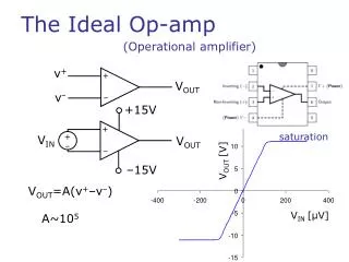
Differential Amplifier Circuit Model in linear region V0 V+ + A AV1 Ri V + + + V1 V0 But if A ~ , is the output infinite? “Very high gain” THE DIFFERENTIAL AMPLIFIER “Differential” V0 depends only on difference (V+ V-) The output cannot be larger than the supply voltages. It will limit or “clip” if we attempt to go too far. We call the limits of the output the “rails”.
Circuit model gives the essential linear part • But V0 cannot rise above some physical voltage related to the positive power supply VCC (“ upper rail”) V0 < V+RAIL • And V0 cannot go below most negative power supply, VEE i.e., limited by lower “rail” V0 > V-RAIL (a) I-V near origin (b) I-V over wider range upper “rail” V0 (V) V0 (V) 3 0.2 2 + + VIN 0.1 1 V0 VIN(V) VIN(V) 1 3 3 2 1 2 10 30 30 20 10 20 1 lower “rail” 2 .2 3 WHAT ARE I-V CHARACTERISTICS OF AN ACTUAL HIGH-GAIN DIFFERENTIAL AMPLIFIER ? Example: Amplifier with gain of 105, with max V0 of 3V and min V0 of 3V.
V0 VIN + NEGATIVE FEEDBACK THE VOLTAGE FOLLOWER Negative feedback Stabilizes the output
Fundamentally pushes toward stability Fundamentally pushes toward instability or bi-stability NEGATIVE FEEDBACK Familiar examples of negative feedback: Thermostat controlling room temperature Driver controlling direction of automobile Photochromic lenses in eyeglasses Familiar examples of positive feedback: Microphone “squawk” in room sound system Mechanical bi-stability in light switches Thermonuclear reaction in H-bomb
V0 CANNOT , BUT A V+ V() in order that V0 = A(V+ V) iIN(-) @ ( 1 ) V V + - A V0 iIN(+) Finiteinfinitemust be zero + EASY WAY TO GET ANSWERFOR OP-AMP CIRCUITS “Ideal Op-Amp Technique”: Why? (a) RIN large by design (b) V+ V() voltage difference acrossRIN 0 Why? With ideal op-amp technique we can analyze all sorts of negative feedback
EXAMPLES USING IDEAL OP-AMP TECHNIQUE The non-inverting amplifier
EXAMPLES USING IDEAL OP-AMP TECHNIQUE ???????????????????