Download
1 / 1
10 likes | 83 Views
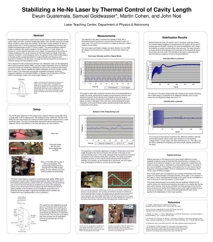
Stabilizing a He-Ne Laser by Thermal Control of Cavity Length Ewuin Guatemala, Samuel Goldwasser*, Martin Cohen, and John Noé Laser Teaching Center, Department of Physics & Astronomy. Abstract. Measurements

E N D
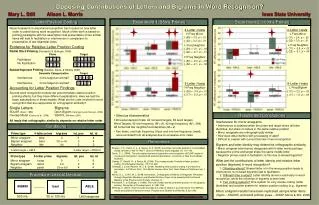
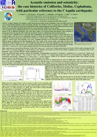
Stabilizing a He-Ne Laser by Thermal Control of Cavity LengthEwuin Guatemala, Samuel Goldwasser*, Martin Cohen, and John NoéLaser Teaching Center, Department of Physics & Astronomy Abstract Measurements The intensity of the laser is tracked from startup to finish with a photodetector which produces a current when the beam is upon its active area. The current is converted to a voltage by placing a resistor between its two leads. The error signal and heater voltages are taken directly from the PCB. All voltages are interfaced to a computer to track these values over time. Stabilization Results Precision optical experiments require lasers whose frequency and/or intensity remain highly stable over time. Common sealed tube helium neon (He-Ne) lasers do not fulfill these conditions unless they are modified. He-Ne laser cavities between 20-30cm in length produce two or three longitudinal modes that are amplified by the Neon gas' Doppler-broadened gain profile (1.5 GHz in width). The spacing between adjacent modes is related to the cavity's length (L) by the equation ν = nc/2L where ν is frequency, c is the speed of light and n is an integer corresponding to the number of modes oscillating in the cavity. However, as the laser heats, the length of the tube expands resulting in mode sweeping, that is, the position of the modes shifts relative to the gain profile causing fluctuations in output intensity and frequency. One approach to stabilize a He-Ne laser is to keep the thermal expansion of the tube to a minimum using a thermal feedback circuit. Since adjacent modes produced by the laser are orthogonal, they can be segregated with a polarizing beam splitter (PBS), and their relative intensities serve as indicators of how the modes are sweeping underneath the gain profile. A proportional-integral (PI) circuit can be used to regulate the relative intensities of the two modes, locking them in place. This setup was successfully completed and tested, achieving frequency stability to an estimated 25MHz, or 55ppb of the He-Ne laser’s 474THz (632nm wavelength) output, and cavity length stability of 12nm. Before locking the laser, the setup is set to “pre-heat” mode for at least five minutes before feedback is introduced into the system. At the end of preheat (around the 600th second), the circuit is switched to “lock” mode, and stability is usually reached within a few seconds. The laser intensity is measured from the beginning of the operation and is tracked for about 30 minutes into lock mode. The intensity of the laser is measured both with and without a polarizer in front of the photodetector. How Laser Intensity and Error Signal Relate Intensity without a polarizer Caption: The gain profile of Neon gas is Gaussian in shape and is 1.5 GHz in width. The longitudinal modes are extremely narrow in comparison, and are separated by 645MHz for a 24cm length cavity. The intensity with which each mode is amplified by the medium depends on its position underneath the gain profile (it is highest at the center and smaller at the ends). This graph is taken with a polarizer placed in front of the photodetector to isolate one mode, producing the largest contrast between minimum and maximum intensity. Each extreme is an indication that one mode is predominantly lasing, and should correspond to an extreme in the error signal. As seen in the graph, this is the case, demonstrating the proper integration of the optical (beam splitter and photodiodes) and electronic components of the setup. The intensity of the laser slowly builds after startup and is clearly oscillating over a wide range in comparison to its stabilized intensity. Once in lock mode, the rms fractional voltage was cut to 1%. Intensity with a polarizer Setup Behavior of the Setup During Lock The He-Ne laser stabilized for the project was a Spectra-Physics model 088, 24cm in length with 1mW of output power. The heating coil was made from 190 feet of 30 AWG (20-ohm total resistance) enamel-insulated magnet wire obtained from a chain electronics store. The wire is wound bifilar around the tube to avoid inducing magnetic effects, and adheres to the tube with epoxy at a few locations. Bare tube. The inclusion of the polarizer maximizes the difference between intensity minima and maxima, which in this case resulted in a rms fractional voltage of 52%. In lock mode, this value diminished to 4%. This value can be used to estimate the frequency and cavity length stability achieved by the setup. Tube with heater with the back beam aligned with the PBS The apparatus is constantly adjusting to changes in temperature and cavity length throughout the time it is locked. The intensity of the laser is still varying minutely when in lock mode, although these fluctuations are small in comparison to the intensity shifts when unlocked. The setup is sensitive enough to produce an error signal closely following these changes in intensity. For example, as the intensity fell in second 40, the error signal rose, prompting an increase in current across the heater. Stability Estimates Making estimates of the frequency and cavity length stabilities is made relatively simple by using the data from the polarized lock. A change from a minimum to a maximum voltage (or vice versa) represents a switch from one mode to another, which is equivalent to a free spectral range (c / 2L) which in this case is 645Mhz. If the voltage is fluctuating only 4%, this means that the frequency is fluctuating 25Mhz, which in comparison to the frequency of the He-Ne Laser (474Thz) is 55ppb. Each mode switch also corresponds to an increase or decrease in the cavity length of a half wavelength of the light (316nm). Once again, a 4% variation in this value is 12nm, meaning that the length of the cavity can be controlled on a very small scale for slow fluctuations in cavity length. This project demonstrates how a simple thermal feedback method can be used to reduce the intensity and frequency fluctuations of a sealed tube He-Ne laser within minutes, and can be controlled over long periods of time. Further work can be done to further limit frequency and cavity length fluctuations such as the use of insulation. Or, some of the principals learned here can be applied to the stabilization of other laser systems. Photo of the PBS with the pair of silicon photodiodes. Two orthogonally polarized beams emerge from the PBS at right angles. A mirror reflects one of the beams towards the photodiode. The laser’s back beam is coupled to a polarizing beam splitter (PBS) which produces two beams with orthogonal polarizations. Each beam goes into a photodiode, producing two currents which are compared by the proportional part of the PI circuit producing an amplified error signal. The integrating portion of the circuit sums the error signal over time and has the effect of adding stability to the feedback circuit (a feedback circuit with only a proportional term provides a signal that oscillates before it settles; the integral term has a damping effect on this oscillation). Left is a Scanning Fabry-Perot Interferometer (SFPI) whose cavity length is varied by a PZT driven by a function generator. It also contains a photodiode to measure the intensities of the light resonating within the cavity. The voltage across the photodiode can thus be tracked on an oscilloscope (right) to display the longitudinal modes within the cavities and their relative intensities. Each pair of peaks in the photo on the right represents one of the modes of the laser light resonant in the SFPI. These peaks rise and fall indicating the “sweeping” of the modes across the laser’s gain profile; they hold steady when the laser is locked. References A. Lindberg, “Mode frequency pulling in He–Ne lasers American Journal of Physics,”Am. J. Physics. 67, 350 (1999) Control Tutorials for Matlab and Simulink: PID Tutorial , April 2010 http://www.engin.umich.edu/class/ctms/pid/pid.htm F. Stanek, R.G. Tobin, C.L. Foiles, “Stabilization of a multimode He-Ne laser: A vivid demonstration of thermal feedback,” Am. J. Physics. 61, 932 (1993) G.A. Woosley, M.Y. Sulaiman, M. Mokhsin, “Correlation of changes in laser tube temperature, cavity length, and beam polarization for an internal-mirror helium-neon laser,” Am. J. Physics. 50, 936 (1982) S. Goldwasser, Sam’s Laser FAQ, April 2010. http://www.repairfaq.org/sam/lasersam.htm The signal from the integrating op-amp goes to a transistor which powers the heater. The amount of current going to the heater is constantly being adjusted according to the difference in intensities of each mode. The trim-pots associated with each op-amp can be adjusted to achieve the desired ratio of mode intensities. A picture of the setup shows the laser wound with the red heater coil, and the yellow Ethernet cord connecting the photodiodes to the circuit in the background. The PI circuit is contained on a small 4cm X 5cm printed circuit board. The wires in a spare Ethernet cord are used to connect the PCB to the photodiodes and heater. * Dr. Goldwasser, of Bala-Cynwyd, PA, is the author of the widely-knowninternet resource Sam's Laser FAQ. He provided the laser tube and circuitboard for this project, and the Fabry-Perot analyzer. Further informationabout the circuit design may be found at the Laser FAQ web site.