Download
1 / 8
90 likes | 217 Views
Example: Test Stand Shadowing a SLIC. coaxial. UTP. CIC. SFO. pigtail. Front Ends. Alpha. pigtail. undo. MBT. SFO. SLIC. Target. L1 (SCL). Test Stand. (*). Alpha. SFO. MBT/Alpha outputs not shown. MBT. SLIC. pigtail. Shadow. (*).

E N D
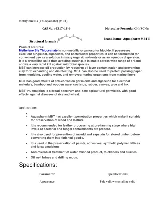
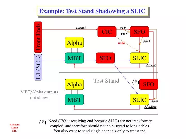
Example: Test Stand Shadowing a SLIC coaxial UTP CIC SFO pigtail Front Ends Alpha pigtail undo MBT SFO SLIC Target L1 (SCL) Test Stand (*) Alpha SFO MBT/Alpha outputs not shown MBT SLIC pigtail Shadow (*) Need SFO at receiving end because SLICs are not transformer coupled, and therefore should not be plugged to long cables. You also want to send single channels only to test stand. A.Maciel L2mu NIU
A.Maciel L2mu NIU SFO Usage as Central Scint. Fan Out to SLICs Input CIC Channels Destination SLIC channels East Octant Scints come in three CIC single channels East side (050,0) East top (051,0) East bottom (056,0) L1 trigger data A-layer east BC- ” oct.0 BC- ” oct.7 S F O BC- ” oct.1 (051,056) L1 trigger data (051,056) A-layer east West ibid. with (52,0) (53,0) (55,0) as inputs BC- ” oct.6 20 cm Needs two SFO’s , one East, one West. Each SFO needs two “pigtails” of type (male)**3 - permanent – plus 2* 30cm cables (male)**2 To SLIC Length = 12.5m 20 cm
A.Maciel L2mu NIU SFO Usage as Central Scint. Fan Out to Shadow SLICs Input CIC Channels Destination SLIC channels To target (L1) SLIC L1 trigger data A-layer east BC- ” oct.0 BC- ” oct.7 S F O To shadow SLIC (L1) at Test Stand S F O East side (050,0) East top (051,0) East bottom (056,0) To shadow SLIC (L1) at Test Stand BC- ” oct.1 (051,056) L1 trigger data to target SLIC (051,056) A-layer east To shadow SLIC (L1) at Test Stand BC- ” oct.6 obs: Scint. data from CIC comes in single channel Both SFO’s are on CIC crate 20 cm To SLIC Length = 12.5m all male connectors 20 cm
A.Maciel L2mu NIU SFO Usage for Shadowing any one SLIC 20 cm To SLIC Length = 1m all male 6 14x30m 20 cm SFO SFO 3 times 3 times CIC SLIC SFO SFO 3 times 3 times Image SLIC at Test Stand Generic Input; 6 double channels from CIC crate Two SFOs at CIC crate Two SFOs at Test Stand SFO 3 times SLIC Target SLIC at Muon Crate 20 cm from CIC Length = 1m all male SFO 6 3 times 20 cm 20 cm To SLIC Length = 20cm female ! 6 20 cm
A.Maciel L2mu NIU Pigtail Totals Summary CIC to SFO SFO 20 cm Central Scint Fanout set permanently from CIC crate to Muon Crate total = 4 12.5m All (male) 20 cm SFO to SLIC SFO 20 cm SLIC Shadowing from CIC crate to Muon Crate. Female connector on twochan end total = 6 20cm (female) 20 cm SLIC Shadowing Within Muon crates Length = 1m total = 6 SFO 20 cm 1m SLIC Shadowing T.Stand to T.Stand Length = 1m total = 6 All (male) 20 cm
Level-2 Hotlink Totals (*) includes 10% added
Shadowing a Generic SLIC • Step 1;convert double inputs • to 14 singles. 7(12) pigtails • Generic SLIC has 8 • double channel inputs; • (SCL,idle) • (ch.2 , ch.3) • ••• • (ch.14,ch.15) one single • Step 2;make 14 data copies • 6x(12) = 1st dedicated SFO • 6x(12) = 2nd dedicated SFO • 2x(12) = borrowed SFO seven doubles • Step 3;connect 14 channels • PPMCH2 PPFCH2 • PP has chs.2•••15 specified • Step 4;convert 14 single inputs • to 7 doubles [7(21) pigtails] • acc. to specific SLIC under study, • re-connect target SLIC • Step 5;repeat step 4 at Test Stand, • connect shadow SLIC. 7(12) pigtails • Step 6; A.Maciel L2mu NIU
A.Maciel L2mu NIU UTP Cable Terminations Active (signal) pair is transformer coupled on both input and output Idle pairs grounded and capacitor terminated (rec.) to eliminate DCs from ground offsets