Download
1 / 74
990 likes | 1.74k Views
Wireless & Mobile Communications Chapter 2: Wireless Transmission. Frequencies Signals Antennas Signal propagation Multiplexing Spread spectrum Modulation Cellular systems. Spectrum Allocation. twisted pair. VLF = Very Low Frequency UHF = Ultra High Frequency

E N D
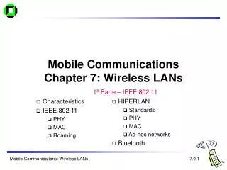
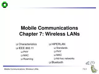
Wireless & Mobile CommunicationsChapter 2: Wireless Transmission Frequencies Signals Antennas Signal propagation Multiplexing Spread spectrum Modulation Cellular systems
Spectrum Allocation twisted pair VLF = Very Low Frequency UHF = Ultra High Frequency LF = Low Frequency SHF = Super High Frequency MF = Medium Frequency EHF = Extra High Frequency HF = High Frequency UV = Ultraviolet Light VHF = Very High Frequency Relationship between frequency ‘f’ and wave length ‘’ : = c/f where c is the speed of light 3x10⁸m/s coax cable optical transmission 1 Mm 300 Hz 10 km 30 kHz 100 m 3 MHz 1 m 300 MHz 10 mm 30 GHz 100 m 3 THz 1 m 300 THz VLF LF MF HF VHF UHF SHF EHF infrared UV visible light ICS 243E - Ch.2 Wireless Transmission
Frequencies Allocated for Mobile Communication • VHF & UHF ranges for mobile radio • allows for simple, small antennas for cars • deterministic propagation characteristics • less subject to weather conditions –> more reliable connections • SHF and higher for directed radio links, satellite communication • small antennas with directed transmission • large bandwidths available • Wireless LANs use frequencies in UHF to SHF spectrum • some systems planned up to EHF • limitations due to absorption by water and oxygen molecules • weather dependent fading, signal loss caused by heavy rainfall, etc. ICS 243E - Ch.2 Wireless Transmission
Allocated Frequencies • ITU-R holds auctions for new frequencies, manages frequency bands worldwide for harmonious usage (WRC - World Radio Conferences) ICS 243E - Ch.2 Wireless Transmission
Signals I • physical representation of data • function of time and location • signal parameters: parameters representing the value of data • classification • continuous time/discrete time • continuous values/discrete values • analog signal = continuous time and continuous values • digital signal = discrete time and discrete values • signal parameters of periodic signals: period T, frequency f=1/T, amplitude A, phase shift • sine wave as special periodic signal for a carrier: s(t) = At sin(2 ft t + t) ICS 243E - Ch.2 Wireless Transmission
Fourier Representation of Periodic Signals 1 1 0 0 t t ideal periodic signal real composition (based on harmonics) ICS 243E - Ch.2 Wireless Transmission
Signals II • Different representations of signals • amplitude (amplitude domain) • frequency spectrum (frequency domain) • phase state diagram (amplitude M and phase in polar coordinates) • Composite signals mapped into frequency domain using Fourier transformation • Digital signals need • infinite frequencies for perfect representation • modulation with a carrier frequency for transmission (->analog signal!) Q = M sin A [V] A [V] t[s] I= M cos f [Hz] ICS 243E - Ch.2 Wireless Transmission
Antennas • Antennas are used to radiate and receive EM waves (energy) • Antennas link this energy between the ether and a device such as a transmission line (e.g., coaxial cable) • Antennas consist of one or several radiating elements through which an electric current circulates • Types of antennas: • omnidirectional • directional • phased arrays • adaptive • optimal • Principal characteristics used to characterize an antenna are: • radiation pattern • directivity • gain • efficiency ICS 243E - Ch.2 Wireless Transmission
y z x Isotropic Antennas • Isotropic radiator: equal radiation in all directions (three dimensional) - only a theoretical reference antenna • Real antennas always have directive effects (vertical and/or horizontal) • Radiation pattern: measurement of radiation around an antenna ideal isotropic radiator ICS 243E - Ch.2 Wireless Transmission
/2 Omnidirectional Antennas: simple dipoles • Real antennas are not isotropic radiators but, e.g., dipoles with lengths /4, or Hertzian dipole: /2 (2 dipoles) shape/size of antenna proportional to wavelength • Example: Radiation pattern of a simple Hertzian dipole • Gain: ratio of the maximum power in the direction of the main lobe to the power of an isotropic radiator (with the same average power) /4 y y z simple dipole x z x side view (xy-plane) side view (yz-plane) top view (xz-plane) ICS 243E - Ch.2 Wireless Transmission
Directional Antennas • Often used for microwave connections (directed point to point transmission) or base stations for mobile phones (e.g., radio coverage of a valley or sectors for frequency reuse) y y z directed antenna x z x side view (xy-plane) side view (yz-plane) top view (xz-plane) z z sectorized antenna x x top view, 3 sector top view, 6 sector ICS 243E - Ch.2 Wireless Transmission
/4 /2 /4 /2 /2 /2 + + ground plane Array Antennas • Grouping of 2 or more antennas to obtain radiating characteristics that cannot be obtained from a single element • Antenna diversity • switched diversity, selection diversity • receiver chooses antenna with largest output • diversity combining • combine output power to produce gain • cophasing needed to avoid cancellation ICS 243E - Ch.2 Wireless Transmission
Signal Propagation Ranges • Transmission range • communication possible • low error rate • Detection range • detection of the signal possible • no communication possible, high error rate • Interference range • signal may not be detected • signal adds to the background noise sender transmission distance detection interference ICS 243E - Ch.2 Wireless Transmission
reflection scattering diffraction Signal Propagation I • Radio wave propagation is affected by the following mechanisms: • reflection at large obstacles • scattering at small obstacles • diffraction at edges ICS 243E - Ch.2 Wireless Transmission
shadowing Signal Propagation II • The signal is also subject to degradation resulting from propagation in the mobile radio environment. The principal phenomena are: • pathloss due to distance covered by radio signal (frequency dependent, less at low frequencies) • fading (frequency dependent, related to multipath propagation) • shadowing induced by obstacles in the path between the transmitted and the receiver ICS 243E - Ch.2 Wireless Transmission
Signal Propagation III • Interference from other sources and noise will also impact signal behavior: • co-channel (mobile users in adjacent cells using same frequency) and adjacent (mobile users using frequencies adjacent to transmission/reception frequency) channel interference • ambient noise from the radio transmitter components or other electronic devices, • Propagation characteristics differ with the environment through and over which radio waves travel. Several types of environments can be identified (dense urban, urban, suburban and rural) and are classified according to the following parameters: • terrain morphology • vegetation density • buildings: density and height • open areas • water surfaces ICS 243E - Ch.2 Wireless Transmission
Pathloss I • Free-space pathloss: To define free-space propagation, consider an isotropic source consisting of a transmitter with a power Pt W. At a distance ‘d’ from this source, the power transmitted is spread uniformly on the surface of a sphere of radius ‘d’. The power density at the distance ‘d’ is then as follows: Sr = Pt/4pd2 • The power received by an antenna at a distance ‘d’ from the transmitter is then equal to: Pr = PtAe/4pd2 where Ae is the effective area of the antenna. ICS 243E - Ch.2 Wireless Transmission
Pathloss II • Noting that Ae = Gr/(4p/l2) where Gr is the gain of the receiver • And if we replace the isotropic source by a transmitting antenna with a gain Gt the power received at a distance ‘d’ of the transmitter by a receiving antenna of gain Gr becomes: Pr = PtGrGt/[4p(d/l)]2 • In decibels the propagation pathloss (PL) is given by: PL(db) = -10log10(Pr/Pt) = -10log10(GrGt/[4p(d/l)]2) • This is for the ideal case and can only be applied sensibly to satellite systems and short range LOS propagation. ICS 243E - Ch.2 Wireless Transmission
Multipath Propagation I • Signal can take many different paths between sender and receiver due to reflection, scattering, diffraction • Positive effects of multipath: • enables communication even when transmitter and receiver are not in LOS conditions - allows radio waves effectively to go through obstacles by getting around them thereby increasing the radio coverage area signal at sender signal at receiver ICS 243E - Ch.2 Wireless Transmission
Multipath Propagation II • Negative effects of multipath: • Time dispersion or delay spread: signal is dispersed over time due signals coming over different paths of different lengths Causes interference with “neighboring” symbols, this is referred to as Inter Symbol Interference (ISI) multipath spread (in secs) = (longest1 – shortest2)/c For a 5ms symbol duration a 1ms delay spread means about a 20% intersymbol overlap. • The signal reaches a receiver directly and phase shifted (due to reflections) Distorted signal depending on the phases of the different parts, this is referred to as Rayleigh fading, due to the distribution of the fades. It creates fast fluctuations of the received signal (fast fading). • Random frequency modulation due to Doppler shifts on the different paths. Doppler shift is caused by the relative velocity of the receiver to the transmitter, leads to a frequency variation of the received signal. ICS 243E - Ch.2 Wireless Transmission
Effects of Mobility • Channel characteristics change over time and location • signal paths change • different delay variations of different signal parts • different phases of signal parts quick changes in the power received (short term fading) • Additional changes in • distance to sender • obstacles further away slow changes in the average power received (long term fading) long term fading power t short term fading ICS 243E - Ch.2 Wireless Transmission
Multiplexing Techniques • Multiplexing techniques are used to allow many users to share a common transmission resource. In our case the users are mobile and the transmission resource is the radio spectrum. Sharing a common resource requires an access mechanism that will control the multiplexing mechanism. • As in wireline systems, it is desirable to allow the simultaneous transmission of information between two users engaged in a connection. This is called duplexing. • Two types of duplexing exist: • Frequency division duplexing (FDD), whereby two frequency channels are assigned to a connection, one channel for each direction of transmission. • Time division duplexing (TDD), whereby two time slots (closely placed in time for duplex effect) are assigned to a connection, one slot for each direction of transmission. ICS 243E - Ch.2 Wireless Transmission
Multiplexing channels ki • Multiplexing in 3 dimensions • time (t) (TDM) • frequency (f) (FDM) • code (c) (CDM) • Goal: multiple use of a shared medium k1 k2 k3 k4 k5 k6 c t c s1 t s2 f f c t s3 f ICS 243E - Ch.2 Wireless Transmission
Narrowband versus Wideband • These multiple access schemes can be grouped into two categories: • Narrowband systems - the total spectrum is divided into a large number of narrow radio bands that are shared. • Wideband systems - the total spectrum is used by each mobile unit for both directions of transmission. Only applicable for TDM and CDM. ICS 243E - Ch.2 Wireless Transmission
Frequency Division Multiplexing (FDM) • Separation of the whole spectrum into smaller frequency bands • A channel gets a certain band of the spectrum for the whole time – orthogonal system • Advantages: • no dynamic coordination necessary, i.e., sync. and framing • works also for analog signals • low bit rates – cheaper, delay spread • Disadvantages: • waste of bandwidth if the traffic is distributed unevenly • inflexible • guard bands • narrow filters k1 k2 k3 k4 k5 k6 c f t ICS 243E - Ch.2 Wireless Transmission
Time Division Multiplexing (TDM) • A channel gets the whole spectrum for a certain amount of time – orthogonal system • Advantages: • only one carrier in themedium at any time • throughput high - supports bursts • flexible – multiple slots • no guard bands ?! • Disadvantages: • Framing and precise synchronization necessary • high bit rates at each Tx/Rx k1 k2 k3 k4 k5 k6 c f t ICS 243E - Ch.2 Wireless Transmission
Hybrid TDM/FDM • Combination of both methods • A channel gets a certain frequency band for a certain amount of time (slot). • Example: GSM, hops from one band to another each time slot • Advantages: • better protection against tapping (hopping among frequencies) • protection against frequency selective interference • Disadvantages: • Framing and sync. required k1 k2 k3 k4 k5 k6 c f t ICS 243E - Ch.2 Wireless Transmission
Code Division Multiplexing (CDM) • Each channel has a unique code (not necessarily orthogonal) • All channels use the same spectrum at the same time • Advantages: • bandwidth efficient • no coordination and synchronization necessary • good protection against interference and tapping • Disadvantages: • lower user data rates due to high gains required to reduce interference • more complex signal regeneration k1 k2 k3 k4 k5 k6 c f t ICS 243E - Ch.2 Wireless Transmission 2.19.1
Issues with CDM • CDM has a soft capacity. The more users the more codes that are used. However as more codes are used the signal to interference (S/I) ratio will drop and the bit error rate (BER) will go up for all users. • CDM requires tight power control as it suffers from far-near effect. In other words, a user close to the base station transmitting with the same power as a user farther away will drown the latter’s signal. All signals must have more or less equal power at the receiver. • Rake receivers can be used to improve signal reception. Time delayed versions (a chip or more delayed) of the signal (multipath signals) can be collected and used to make bit level decisions. • Soft handoffs can be used. Mobiles can switch base stations without switching carriers. Two base stations receive the mobile signal and the mobile is receiving from two base stations (one of the rake receivers is used to listen to other signals). • Burst transmission - reduces interference ICS 243E - Ch.2 Wireless Transmission
Types of CDM I • Two types exist: • Direct Sequence CDM (DS-CDM) • spreads the narrowband user signal (Rbps) over the full spectrum by multiplying it by a very wide bandwidth signal (W). This is done by taking every bit in the user stream and replacing it with a pseudonoise (PN) code (a long bit sequence called the chip rate). The codes are orthogonal (or approx.. orthogonal). • This results in a processing gain G = W/R (chips/bit). The higher G the better the system performance as the lower the interference. G2 indicates the number of possible codes. Not all of the codes are orthogonal. ICS 243E - Ch.2 Wireless Transmission
Types of CDM II • Frequency hopping CDM (FH-CDM) • FH-CDM is based on a narrowband FDM system in which an individual user’s transmission is spread out over a number of channels over time (the channel choice is varied in a pseudorandom fashion). If the carrier is changed every symbol then it is referred to as a fast FH system, if it is changed every few symbols it is a slow FH system. ICS 243E - Ch.2 Wireless Transmission
Orthogonality and Codes • An m-bit PN generator generates N=2m - 1 different codes. • Out of these codes only ‘m’ codes are orthogonal -> zero cross correlation. • For example a 3 bit shift register circuit shown below generates N=7 codes. ICS 243E - Ch.2 Wireless Transmission
Orthogonal Codes • A pair of codes is said to be orthogonal if the cross correlation is zero: Rxy(0) = 0 . • For two m-bit codes: x1,x2,x3,...,xm and y1,y2,y3,...,ym: For example: x = 0011 and y = 0110. Replace 0 with -1, 1 stays as is. Then: x = -1 -1 1 1 y = -1 1 1 -1 ----------------- Rxy(0) = 1 -1 +1 -1 = 0 ICS 243E - Ch.2 Wireless Transmission
Example of an Orthogonal Code: Walsh Codes • In 1923 J.L. Walsh introduced a complete set of orthogonal codes. To generate a Walsh code the following two steps must be followed: • Step 1: represent a NxN matrix as four quadrants (start off with 2x2) • Step 2: make the first, second and third quadrants indentical and invert the fourth ICS 243E - Ch.2 Wireless Transmission
Modulation • Digital modulation • digital data is translated into an analog signal (baseband) • ASK, FSK, PSK - main focus in this chapter • differences in spectral efficiency, power efficiency, robustness • Analog modulation • shifts center frequency of baseband signal up to the radio carrier • Motivation • smaller antennas (e.g., /4) • Frequency Division Multiplexing • medium characteristics • Basic schemes • Amplitude Modulation (AM) • Frequency Modulation (FM) • Phase Modulation (PM) ICS 243E - Ch.2 Wireless Transmission
Modulation and Demodulation analog baseband signal digital data digital modulation analog modulation radio transmitter 101101001 radio carrier analog baseband signal digital data analog demodulation synchronization decision radio receiver 101101001 radio carrier ICS 243E - Ch.2 Wireless Transmission
Digital Modulation • Modulation of digital signals known as Shift Keying • Amplitude Shift Keying (ASK): • very simple • low bandwidth requirements • very susceptible to interference • Frequency Shift Keying (FSK): • needs larger bandwidth • Phase Shift Keying (PSK): • more complex • robust against interference 1 0 1 t 1 0 1 t 1 0 1 t ICS 243E - Ch.2 Wireless Transmission
Advanced Frequency Shift Keying • bandwidth needed for FSK depends on the distance between the carrier frequencies • special pre-computation avoids sudden phase shifts MSK (Minimum Shift Keying) • bit separated into even and odd bits, the duration of each bit is doubled • depending on the bit values (even, odd) the higher or lower frequency, original or inverted is chosen • the frequency of one carrier is twice the frequency of the other • even higher bandwidth efficiency using a Gaussian low-pass filter GMSK (Gaussian MSK), used in GSM ICS 243E - Ch.2 Wireless Transmission
Example of MSK 0 1 1 0 1 0 1 bit data even 0 1 0 1 even bits odd 0 0 1 1 signal h n n hvalue - - + + odd bits low frequency h: high frequency n: low frequency +: original signal -: inverted signal highfrequency MSK signal t No phase shifts! ICS 243E - Ch.2 Wireless Transmission
Q I 1 0 Q 11 10 I 00 01 Advanced Phase Shift Keying • BPSK (Binary Phase Shift Keying): • bit value 0: sine wave • bit value 1: inverted sine wave • very simple PSK • low spectral efficiency • robust, used e.g. in satellite systems • QPSK (Quadrature Phase Shift Keying): • 2 bits coded as one symbol • symbol determines shift of sine wave • needs less bandwidth compared to BPSK • more complex • Often also transmission of relative, not absolute phase shift: DQPSK - Differential QPSK (IS-136, PACS, PHS) A t 01 11 10 00 ICS 243E - Ch.2 Wireless Transmission
Quadrature Amplitude Modulation • Quadrature Amplitude Modulation (QAM): combines amplitude and phase modulation • it is possible to code n bits using one symbol • 2n discrete levels, n=2 identical to QPSK • bit error rate increases with n, but less errors compared to comparable PSK schemes Example: 16-QAM (4 bits = 1 symbol) • Symbols 0011 and 0001 have the same phase, but different amplitude. 0000 and 1000 have different phase, but same amplitude. • used in standard 9600 bit/s modems 0010 Q 0001 0011 0000 I 1000 ICS 243E - Ch.2 Wireless Transmission
Spread spectrum technology: CDM • Problem of radio transmission: frequency dependent fading can wipe out narrow band signals for duration of the interference • Solution: spread the narrow band signal into a broad band signal using a special code • protection against narrow band interference protection against narrowband interference • Side effects: • coexistence of several signals without dynamic coordination • tap-proof • Alternatives: Direct Sequence, Frequency Hopping signal power interference spread signal power spread interference detection at receiver f f ICS 243E - Ch.2 Wireless Transmission
Effects of spreading and interference P P user signal broadband interference narrowband interference i) ii) f f sender P P P iii) iv) v) f f f receiver ICS 243E - Ch.2 Wireless Transmission 2.28.1
channelquality 2 2 2 2 2 1 frequency spreadspectrum Spreading and frequency selective fading channelquality 2 1 5 6 narrowband channels 3 4 frequency narrow bandsignal guard space spread spectrum channels ICS 243E - Ch.2 Wireless Transmission 2.29.1
DSSS (Direct Sequence Spread Spectrum) I • XOR of the signal with pseudo-random number (chipping sequence) • many chips per bit (e.g., 128) result in higher bandwidth of the signal • Advantages • reduces frequency selective fading • in cellular networks • base stations can use the same frequency range • several base stations can detect and recover the signal • soft handover • Disadvantages • precise power control necessary tb user data 0 1 XOR tc chipping sequence 0 1 1 0 1 0 1 0 1 1 0 1 0 1 = resulting signal 0 1 1 0 1 0 1 1 0 0 1 0 1 0 tb: bit period tc: chip period ICS 243E - Ch.2 Wireless Transmission 2.30.1
DSSS (Direct Sequence Spread Spectrum) II spread spectrum signal transmit signal user data X modulator chipping sequence radio carrier transmitter correlator lowpass filtered signal sampled sums products received signal data demodulator X integrator decision radio carrier chipping sequence receiver ICS 243E - Ch.2 Wireless Transmission 2.31.1
FHSS (Frequency Hopping Spread Spectrum) I • Discrete changes of carrier frequency • sequence of frequency changes determined via pseudo random number sequence • Two versions • Fast Hopping: several frequencies per user bit • Slow Hopping: several user bits per frequency • Advantages • frequency selective fading and interference limited to short period • simple implementation • uses only small portion of spectrum at any time • Disadvantages • not as robust as DSSS • simpler to detect ICS 243E - Ch.2 Wireless Transmission 2.32.1
FHSS (Frequency Hopping Spread Spectrum) II tb user data 0 1 0 1 1 t f td f3 slow hopping (3 bits/hop) f2 f1 t td f f3 fast hopping (3 hops/bit) f2 f1 t tb: bit period td: dwell time ICS 243E - Ch.2 Wireless Transmission 2.33.1
FHSS (Frequency Hopping Spread Spectrum) III spread transmit signal narrowband signal user data modulator modulator frequency synthesizer hopping sequence transmitter narrowband signal received signal data demodulator demodulator hopping sequence frequency synthesizer receiver ICS 243E - Ch.2 Wireless Transmission 2.34.1
Concept of Cellular Communications • In the late 60’s it was proposed to alleviate the problem of spectrum congestion by restructuring the coverage area of mobile radio systems. • The cellular concept does not use broadcasting over large areas. Instead smaller areas called cells are handled by less powerful base stations that use less power for transmission. Now the available spectrum can be re-used from one cell to another thereby increasing the capacity of the system. • However this did give rise to a new problem, as a mobile unit moved it could potentially leave the coverage area (cell) of a base station in which it established the call. This required complex controls that enabled the handing over of a connection (called handoff) to the new cell that the mobile unit moved into. • In summary, the essential elements of a cellular system are: • Low power transmitter and small coverage areas called cells • Spectrum (frequency) re-use • Handoff ICS 243E - Ch.2 Wireless Transmission