Download

1 / 29
290 likes | 526 Views
Reduced gantry size by non-scaling fixed field alternating gradient (FFAG) beam line. Thusday, November 2, 2006. Dejan Trbojevic Brookhaven National Laboratory, Upton, NY, USA. Introduction: Present state of the art gantry design (example in Heidelberg).

E N D
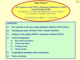
Reduced gantry size by non-scaling fixed field alternating gradient (FFAG) beam line Thusday, November 2, 2006 Dejan Trbojevic Brookhaven National Laboratory, Upton, NY, USA • Introduction: Present state of the art gantry design (example in • Heidelberg). • Basic properties of the non-scaling FFAG. • The non-scaling FFAG gantry – beams with required energies are • transported at the fixed field: • Lattice functions and geometrical constraints. • Matching to the accelerator. • Magnet properties • Possible magnet design for the carbon/proton facility. • Tracking results. • Summary. Dejan Trbojevic
Basic Properties of the Heavy Ion Facility in Heidelberg: Dejan Trbojevic
Basic Properties of the Heavy Ion Facility in Heidelberg: Dejan Trbojevic
Elements of the Gantry in Heidelberg: Dejan Trbojevic
FFAG 06 Port Jefferson r= 7 m Carbon 400 MeV/n Br = 6.347 Tm B=1.6 Tr ~ 4 m B=3.2 Tr ~1.9 m Dejan Trbojevic
Heidelberg Gantry building: FFAG 06 Port Jefferson Dejan Trbojevic
Elements’ weight of the Gantry in Heidelberg: Dejan Trbojevic
Basic Properties of the Non-Scaling FFAG and Gantry Design A . Particle orbitsB. Lattice functions C. Lattice design D. Tracking results Dejan Trbojevic
Particles orbits in the non-scaling (triplet FFAG) 250 MeV proton therapy Dejan Trbojevic
Lattice functions in the triplet design with drifts required for cavities L= 22 cm Very strong focusing: bx,y~1-2 m Dmax~8.8 cm Dejan Trbojevic
Presently being reviewed by the editors of the Phys. Rev. Special Topics Dejan Trbojevic
Lattice functions in the gantry at the central energy (no drift space required- FODO cell) Dejan Trbojevic
Create symmetric orbit offsets in the required energy range Dejan Trbojevic
First step a gantry design:Construct a ring with zero dispersion in the middle of required energy range Dejan Trbojevic
90o+180o solution ‘PTC’ carbon ion tracked orbits are magnified 25 times (‘PTC’ – Polymorphic tracking code by Etienne Forest) Dejan Trbojevic
Betatron Functions through the wholegantry at the central energy Dejan Trbojevic
Smaller angle of the gantry’s first part Dejan Trbojevic
Matching to the accelerator A triplet cell is added at the entrance of the gantry. Matching is provided at the central momentum from the accelerator. At the point of entrance to the gantry's rotating part, the betatron functions are equal and the beam is round for any selected gantry plane angle. In addition the slopes of the ax, ay Dx’=0 betatron functions and dispersion are equal to zero. Zero dispersion is obtained by adjusting the bending angles of the triplet's combined function elements. Two quadrupoles rotate together with the gantry and are on the axis of rotation. They provide matching to the gantry's input betatron functions for each angle of the gantry. Dejan Trbojevic
Magnet Properties and estimated weight: The 40 cm long magnets field requirements do not seem excessive for superconducting magnets. In order to save weight we are investigating building them in a configuration with a simple inner quadrupole surrounded by a thicker outer dipole coil and a very thin dipole coil (active shield) at much larger radius. This is just an old quadrupole design used here as a demonstration 53 T/m The cryostat has an OD=170 mm, and around the whole magnet is a thin warm iron shell to take care of the field not caught by the shield coil. The estimated weight of the magnets is in the range 45-75 kg/m or average ~50 kg/m. The ~30 meter long gantry beam line is ~ 1500 kg. Dejan Trbojevic
Estimated beam pipe size and magnetic field at the major bend a combined function magnet with defocusing gradient y B(T) 5 Estimated beam size 1 - 2 mm FWHM 4 3 B x 2 10 - 12 mm ~-12 mm ~+16 mm f v Maximum beam offsets ~35 mm Dejan Trbojevic
Estimated beam pipe size and the magnetic field values at the opposite bend focusing combined function magnet y B(T) -4 Estimated beam size 1 - 2 mm FWHM -3 -2 x -1 ~1-2 mm f ~-23 mm ~+32 mm ~60 mm v B Maximum beam offsets Dejan Trbojevic
FFAG 06 Port Jefferson Dejan Trbojevic
Super-ferric magnets The magnets might also be built as super ferric magnets with a high temperature superconductor (HTS) racetrack coil distribution. Such a system could operate at temperatures of 35-45 K, and use commercially available cryo-systems without the need for an additional liquid helium service. Dejan Trbojevic
Fermilab permanent magnet design of the combined function magnet Dejan Trbojevic
Tracking studies with different initial conditions Dejan Trbojevic
Tracking results at the end of the gantryin front of the scanning and focusing magnets dp/p=-20% dp/p=+25% dp/p=+20% dp/p=-10% dp/p=-15% dp/p=10% dp/p=+15% dp/p=-5% The smaller ellipses are results for 1 mm initial conditions. dp/p=0 x(mm) Dejan Trbojevic
Summary: • This is an attempt to reduce dramatically the size of the magnets in the • isocentric gantry in the proton therapy facility. • -The non-scaling FFAG gantry is made of the fixed field combined • function magnets. The magnetic field has transversely linear function. • The combined function magnet with focusing gradient has smaller • opposite bending angle. • The large bending dipoles necessary for the carbon therapy are • replaced with many small superconducting combined function • magnets (either Niobium-Tin or super-ferric magnets with HTS tapes). • Tracking results for the expected beam sizes have shown very small • offsets in front of the scanning and focusing magnets above the patient • ( +/- 6 mm) easily adjusted. • -Even in the only proton therapy the size of the magnets could be • reduced. • - Further tracking studies with realistic end fields are required (ZGOUBI). Dejan Trbojevic