Download
1 / 27

E N D
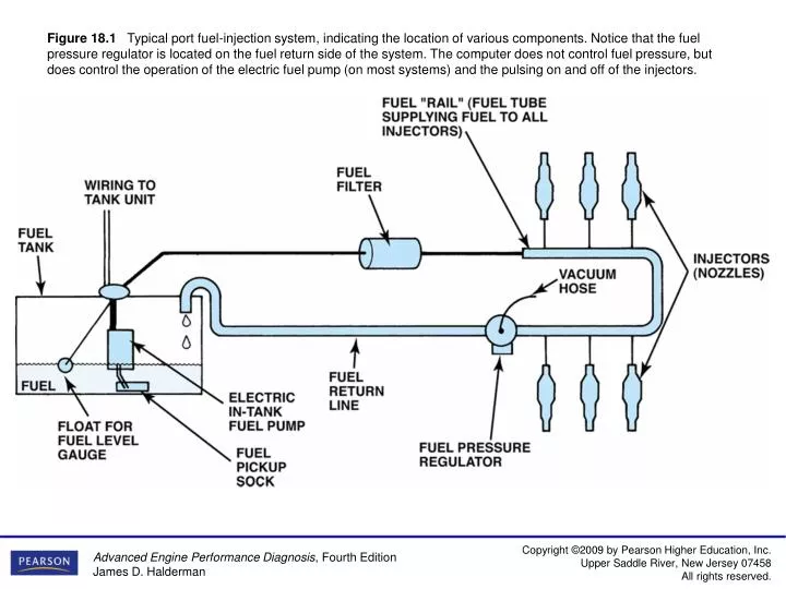
Figure 18.1Typical port fuel-injection system, indicating the location of various components. Notice that the fuel pressure regulator is located on the fuel return side of the system. The computer does not control fuel pressure, but does control the operation of the electric fuel pump (on most systems) and the pulsing on and off of the injectors.
Figure 18.2A dual-nozzle TBI unit on a Chevrolet 4.3-L V-6 engine.
Figure 18.3A typical port fuel-injection system squirts fuel into the low pressure (vacuum) of the intake manifold, about 2 to 3 in. (70 to 100 mm) from the intake valve.
Figure 18.4 The tension of the spring in the fuel-pressure regulator determines the operating pressure on a throttle-body fuel-injection unit.
Figure 18.5The injectors receive fuel and are supported by the fuel rail.
Figure 18.6Cross-section of a typical port fuel-injection nozzle assembly. These injectors are serviced as an assembly only; no part replacement or service is possible except for replacement of external O-ring seals.
Figure 18.7Port fuel injectors spray atomized fuel into the intake manifold about 3 inches (75 mm) from the intake valve.
Figure 18.8A port fuel-injected engine that is equipped with long, tuned intake manifold runners.
Figure 18.10A typical direct-injection system uses two pumps—one low-pressure electric pump in the fuel tank and the other a high-pressure pump driven by the camshaft.
Figure 18.11A typical camshaft-driven high-pressure pump used to increase fuel pressure to 2,000 PSI or higher.
Figure 18.12A gasoline direct-injection (GDI) assembly showing the high-pressure pump plus the fuel rail and injectors which inject fuel directly into the combustion chamber.
Figure 18.13A typical port fuel-injected system showing a vacuum-controlled fuel-pressure regulator.
Figure 18.14A typical fuel-pressure regulator that has a spring that exerts 46 pounds of force against the fuel. If 20 inches of vacuum are applied above the spring, the vacuum reduces the force exerted by the spring on the fuel, allowing the fuel to return to the tank at a lower pressure.
Figure 18.15A lack of fuel flow could be due to a restricted fuel pressure regulator. Notice the fine screen filter. If this filter were to become clogged, higher than normal fuel pressure would occur.
Figure 18.16The fuel-pressure sensor and fuel-temperature sensor are often constructed together in one assembly to help give the PCM the needed data to control the fuel-pump speed.
Figure 18.17A mechanical returnless fuel system. The bypass regulator in the fuel tank controls fuel line pressure.
Figure 18.18A demand delivery system uses an intake regulator.
Figure 18.19A rectangular-shaped fuel rail is used to help dampen fuel system pulsations and noise caused by the injectors opening and closing.
Figure 18.20A multiport fuel injector. Notice that the fuel flows straight through and does not come in contact with the coil windings.
Figure 18.21Each of the eight injectors shown are producing a correct spray pattern for the applications. While all throttle-body injectors spray a conical pattern, most port fuel-injection systems do not.
Figure 18.23A factory replacement unit for a CSFI unit that has individual injectors at the ends that go into the intake manifold instead of poppet valves.
Figure 18.24The small arrows indicate the air bypassing the throttle plate in the closed throttle position. This air is called minimum air. The air flowing through the IAC is the airflow that determines the idle speed.
Figure 18.25Most stepper motors use four wires, which are pulsed by the computer to rotate the armature in steps.
Figure 18.26A GM electronic throttle control system showing the APP and TP sensors and the DC throttle actuator control (TAC) module and PCM. In many systems the motor control is located inside the PCM.
Figure 18.27A typical accelerator pedal position (APP) sensor showing two different output voltage signals that are used by the PCM to determine accelerator pedal position. Two (or three in some applications) are used as a double check because this is a safety-related sensor.