Download
1 / 42
420 likes | 475 Views
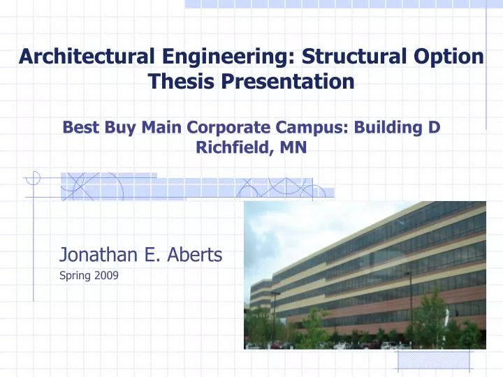
Architectural Engineering: Structural Option Thesis Presentation Best Buy Main Corporate Campus: Building D Richfield, MN. Jonathan E. Aberts Spring 2009. Presentation Outline. Introduction Building description Existing structural conditions Project Proposal Building Redesign Columns

E N D
Architectural Engineering: Structural OptionThesis PresentationBest Buy Main Corporate Campus: Building DRichfield, MN Jonathan E. Aberts Spring 2009
Presentation Outline • Introduction • Building description • Existing structural conditions • Project Proposal • Building Redesign • Columns • PT floor system • Lateral system • Foundation • Cost Comparison • Architectural Comparison • Conclusions
Building Name: Best Buy Main Corporate Building Location: Richfield, MN Function: Office building Occupants: Best Buy corporate employees Architects: Perkins & Will (www.perkinswill.com) Minneapolis, MN Engineers: Opus Northwest (www.opuscorp.com) Minnetonka, MN CM: Opus Northwest Chris Johnson Introduction
Building Description Architecture • Precast curtain wall • Ribbon windows • Curtain wall consists of 6” architectural precast panels tied into the steel structure • Prefinished aluminum closure panel holds the ribbon of windows on each floor
Structural System Floor System • Composite beam framing system • 6¼” slab, 3” 20 gauge deck and 3¼” lightweight concrete • Spray on fireproofing
Structural System Lateral System • Braced frame consist of 3 - W14 columns spliced together at the 3rd and 5th floors • Heavier beams, W16x57
Project Proposal Proposed Solution: • Redesign Best Buy Corporate Building D as a full concrete system • Floor system will be redesigned post-tensioned slab with beams • Columns will also be redesigned into concrete • Lateral bracing system will be shear walls • Goal is to allow for a larger bay size in the short direction of the building • Cost Comparison of structural system • The impact of the change in architecture on the tenant and rentable area
Project Proposal Solution Method: • Utilize ACI 318-05 Building Code Requirements for Structural Concrete • Utilize ADAPT-PT to design beams and slab • Utilize PCA Column and ETABS to design columns and shear walls • Utilize RS Means Building Construction Cost Data for a structural cost analysis • Compare and contrast new vs. old architecture
Building Redesign • Columns • PT floor system • PT beams • Shear Walls • Foundation
Columns • Design floor layout to support larger bays with fewer columns • PCA Columns aided in design of reinforcement • ETABS used to verify column sizing
Columns • 30”x30” columns requiring 32-#11 vertical reinforcing • 24”x24” columns requiring 28-#11 vertical reinforcing
Post-tensioned Slab • Design post-tensioned slab using ADAPT-PT as an aid • Keep slab thickness close to 8” as recommended by span/depth ratio
Post-tensioned Slab • Unit strip method • Determined a 9.5” slab was required • 2 tendons required for first and last 2 spans • 1 tendon for the remaining spans
Post-tensioned Beams • Design post-tensioned beam using ADAPT-PT as an aid • Keep beam thickness close to 27” as recommended by span/depth ratio
Post-tensioned Beams • 2 different beams had to be designed • 2 span (57’6”,57’6”) • 3 span (42’6”,30’,42’6”) • Designed 28” deep for both spans • 27 tendons needed for 2 span and 19 tendons for 3 span
Lateral System • Redesign braced frames into shear walls while maintaining current location
Lateral System • ETABS assisted in the design • Found that a 12” wall was a sufficient thickness • Boundary elements were designed to fit inside the 12” wall
Foundation • Considered, however, not redesigned • Heavier concrete columns and shear walls • Larger piers and slabs • Stronger concrete
Cost Comparisons • A considerable increase in costs of materials and erection • 38%
Architecture Comparisons • Increased open space bays from 42’6” to 57’6” • No fireproofing • Fewer columns for partitioned rooms to work around
Conclusions • New floor system increased bay sizes without sacrificing ceiling/floor height • Cost of new system far exceeds cost of existing system
Acknowledgements • Thesis Advisors: • Dr. Thomas E. Boothby • Industry Contacts: • Gary R. Strand, P.E. - Simpson Gumpertz & Heger • David B. Smith, P.E. - Holbert Apple Associates • Richard Apple, P.E. - Holbert Apple Associates • Other Mentors: • Professor M. Kevin Parfitt • Professor Moses Ling