Download
1 / 19
190 likes | 308 Views
Surface Contouring by phase-shifting real-time holography using photorefractive sillenite crystals. M.R.R. Gesualdi ,D.Soga , M.Muramatsu Optics and Laser Technology Vol 39, pg 98-104 (2007). Journal Club : 9/10/2007 Presenter : Ashwin Kumar Advisors: Prof. Todd Murray

E N D
Surface Contouring by phase-shifting real-time holography using photorefractive sillenite crystals M.R.R. Gesualdi ,D.Soga , M.Muramatsu Optics and Laser Technology Vol 39, pg 98-104 (2007) Journal Club : 9/10/2007 Presenter : Ashwin Kumar Advisors: Prof. Todd Murray Prof. Kamil Ekinci
Contents Introduction to Holography Photorefractive Holography Photorefractive Effect Two-wave mixing Four-Wave Mixing Surface Contouring Rotation Source Method Phase shifting Technique Four-Frame Technique Cellular –Automata Technique Experimental Setup Experimental Results Conclusions
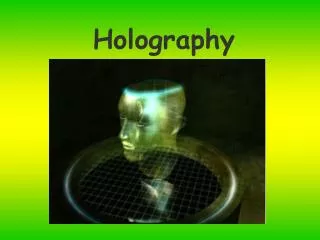
Holography Holography is technique by which a wavefront can be recorded and reconstructed at a later point in the absence of original wavefront Holographic interferometry : Extension of interferometric technique in which atleast one of the waves which interfere is reconstruced by a hologram Advantages : Storing a wavefront for reconstruction at later time Wavefronts separated in time or space can be compared Changes in shape of objects with rough surfaces can be studied
Photorefractive Holography Photorefractive Materials : Changes in index of refraction in accordance with variation in exposed light Photorefractive Effect : Two beams interfere within the crystal to form a sinusoidal intensity pattern Generation of free carriers : Bright region of the intensity pattern Carriers diffuse and/or drift leaving fixed charges behind Carriers are trapped in the dark regions due to introduction of point defects Results in the formation of a nonuniform charge distribution – Space charge field (SCF) SCF modulates the refractive index of the crystal (electro-optic effect) Spatially nonuniform intensity pattern Charge distribution Refractive Index distribution Crystal Space – Charge Field Signal Beam Spatial intensity gradients - Magnitude of photorefractive grating Overall intensity – Speed of formation of grating Absorption Diffusion Trapping Reference Beam
Signal Beam Transmitted Reference Beam Reconstructed Signal Beam Reference Beam Reference Beam Conjugate Signal Beam • Holography involves recording and reconstruction of optical waves (Two- Wave Mixing) • PRC – Dynamic hologram to record the information of optical (signal) beam Plane reference beam can be used to reconstruct the signal Photorefractive Holography Recording and Reconstruction are done simultaneously Reference beam is diffracted into the path of the transmitted signal beam Reference beam matches with the wavefront of the signal beam Writing/Reading Process is reversible No chemical processing is required Short response time and lower noise levels in interferograms
Reconstruction Beam / Second Pump Beam Signal Beam Phase Conjugate of the Signal Beam Reference Beam Photorefractive Holography • Four – Wave Mixing Technique • Two strong pump beams are used to produce a phase conjugate of a weaker probe beam • Four-wave mixing is useful in phase and adaptive amplitude correction and noise filtering
Surface Contouring Shape determination of surfaces – Real-time holographic interferometry Advantages : Non-contact technique to analyze surfaces Provide good reliability, high accuracy and qualitative analysis through visual inspection Holographic contouring methods : Rotation source method (Change in angle of illumination) Hologram of the object is first created The angle of illumination beam is slightly changed and a second hologram is superposed on the first Two sets of light waves reach the observer , Reconstructed wave (Object wave before angle tilt) and wave from the object’s present state Two wave amplitudes add at points where OPD is zero or n and cancel at other points in between. A Reconstructed image covered with a pattern of interference fringes are observed Contour map of the surface of the object
2D Analysis : Object Phase before mirror tilt • 2D Analysis : Object Phase after mirror tilt • Phase Map and height of the object • Sensitivity of this method is given by Tilt angle is sufficiently small Surface Contouring by Rotation- Source Method Measurements of surface shape Difference between the phases before and after of the object illumination beam
Phase-Shifting Technique Interferogram obtained from a slightly concave And irregular surface Phase-Shifting Interferometer Interferogram obtained from a plane Mirror Spatial phase measurement technique Interferogram phase is calculated using holographic interferogram intensities Fringe pattern is complex due to irregularities and intricate shape of the object Four- Frame technique is used to determine the phase The PZT is moved over a distance of /8 inducing a phase shift of /2 to the reference beam Four interference patterns are acquired after stepwise phase shifts of the reference beam
Four Frame Technique • 2D graphic is obtained by representing each phase value by a gray shade intensity • Black corresponding to - and white to • 8 bit imaging system: 256 different gray intensities • Phase wrapping occurs • Noise is filtered using anisotropic sin/cos filter • Phase unwrapping : Cellular-automata technique To determine the phase at each point (i,j), the intensity at each point (i,j) is given by
Phase-Unwrapping Problem • - unwrapped phase • - wrapped phase k – wrap count integer field Phase unwrapping problem consists of singling out the correct k value Relation between wrapped and unwrapped phase • Reconstruction of unwrapped phase is obtained by direct integration • in absence of noise and correctly sampled data • In presence of noise or under sampling, wrapped phase is rotational in nature • Result of the integration depends on the path followed • Presence of rotational components (residues and dipoles) make the solution non-unique • Removal of noise is important in the phase unwrapping problem
Cellular – Automata Technique By repeating these steps, phase progressively unwrapped Each cycle removes one fringe as the local iteration moves the discontinuities to the boundary of the phase field Removed slowly owing to global iteration
Experimental Results All objects were painted with retro-reflector ink to increase the intensity of the scattered laser beam Angle between the recording beams was 45 degs Recording time : 30 secs = 0.36 radians Four Frame Technique ( = 0,/2, ,3 /2) Intensity ratio of Reference: Object Beam = 6.0
Experimental Results Specimen : Bulb of length 30.0 mm and 10.0 mm diameter Change in incidence angle = 0.0001 rad Surface contouring : difference between the max. and min. height is 5.0 mm
Experimental Results Specimen : Chess of length 30.0 mm and 10.0 mm diameter Change in incidence angle = 0.0002 rad Surface contouring : difference between the max. and min. height is 6.0 mm
Experimental Results Specimen : Plug of height 10.0 mm and 20.0 mm diameter Change in incidence angle = 0.00006 rad Surface contouring :Internal border of the piece
Conclusion Phase shifting (RTHI) presents new possibilities of surface topograph BSO crystal in diffusive regimen with configuration exhibiting diffraction anisotropy Height at each point of surface is proportional to the difference of phases due to tilt of the object illuminating beam Results of good quality were obtained and can be improved by fringe analysis Surface height of large objects were determined Errors in measurements : 1. Miscalibration of the phase shifter 2. Spurious reflections and diffractions 3. Quality limitations of the optical elements 4. Nonlinearities and resolution of CCD 5. Air turbulence and vibrations 6. Photorefractive Errors: Temporal modulation of holographic interferograms and temporal fluctuations of thermal dependence on the photorefractive effect