Download
1 / 56
580 likes | 859 Views
Wireless Networking IEEE 802.11 In Depth Module-05. Jerry Bernardini Community College of Rhode Island . Presentation Reference Material. CWNA Certified Wireless Network Administration Official Study Guide, Fourth Edition, Tom Carpenter, Joel Barrett Chapter-4 Pages 153-200

E N D
Wireless NetworkingIEEE 802.11 In DepthModule-05 Jerry Bernardini Community College of Rhode Island Wireless Networking J. Bernardini
Presentation Reference Material • CWNA Certified Wireless Network Administration Official Study Guide, Fourth Edition, Tom Carpenter, Joel Barrett • Chapter-4 Pages 153-200 • The California Regional Consortium for Engineering Advances in Technological Education (CREATE) project Wireless Networking J. Bernardini
Bits, Bytes, Octets, Frames, Packets • Bits =1 or 0 • Bytes = 8 bits • Octets = 8 bits = Byte • Octet is used by telecommunication people • Byte is used by IT people • Frames = grouping of bits at layer-2 • Packets = grouping of bits at layer-3 • Datagrams = another term for packets Wireless Networking J. Bernardini
Coding – ASCII Table Wireless Networking J. Bernardini
OSI data flow CWNA Guide to Wireless LANs, Second EditionCCRI J. Bernardini
IEEE 802.11 Physical Layer Standards • IEEE wireless standards follow OSI model, with some modifications • Data Link layer divided into two sublayers: • Logical Link Control (LLC) sublayer: Provides common interface, reliability, and flow control • Media Access Control (MAC) sublayer: Appends physical addresses to frames • Physical layer divided into two sublayers: • Physical Medium Dependent (PMD) sublayer: Makes up standards for characteristics of wireless medium (such as DSSS or FHSS) and defines method for transmitting and receiving data • Physical Layer Convergence Procedure (PLCP) sublayer: Performs two basic functions • Reformats data received from MAC layer into frame that PMD sublayer can transmit • “Listens” to determine when data can be sent CWNA Guide to Wireless LANs, Second EditionCCRI J. Bernardini
Data Link Layer - Physical Layer- Data Units MSDU (MAC Service Data Unit) (From upper layers 2304 bytes max) 802.2 Logical Link Control LLC Data Link Layer (Layer-2) MPDU (MAC Protocol Data Unit) 802.11 Media Access Control MAC PSDU (PLCP Service Data Unit) (MPDU = PSDU name change to indicated service needed) PLCP PHY Layer Convergence Protocol Physical Layer (Layer-1) PPDU (PLCP Protocol Data Unit) PMD Physical Medium Dependent Modulated Radio Signal PHY = Physical Layer
IEEE 802.3 CSMA/CD vs. IEEE 802.11 CSMA/CA • CSMA/CD is for wired collision handling • CSMA/CA is for wireless collision handling • CSMA = Carrier Sense Multiple Access • CD = Collision Detection • CA = Collision Avoidance • Why do collisions occur? • Answer = Two or more stations transmit at the same time • Why is it important to detect or avoid collisions? • Answer = Because there is data loss and retransmission is necessary • Wired networks are designed for the transmitting station to detect most collisions • Many collisions will not be detected by Wireless networks – therefore avoid collisions
IEEE 802.11 Collision Handling CSMA/CA • In CSMA/CA a Wireless node that wants to transmit performs the following sequence: • Listen on the desired channel. • If channel is idle (no active transmitters) it sends a packet. • If channel is busy the node waits random time until transmission stops and then waits an additional time period. • If the channel is still idle at the end of the time period the node transmits its packet otherwise it repeats the process defined in 3 above until it gets a free channel. • Additional support mechanisms such as ACK, RTS/CTS can be used but increase overhead noticeably.
CSMA/CA Collision Handling • 802.11 standard employs half-duplex radios-radios capable of transmission or reception-but not both simultaneously Wired LAN Listening 1 AP-1 Transmitting Data Frames Access Points 2 Listening Wireless Client Transmitting
Two Kinds of Carrier Sensing Mechanisms • Physical Carrier Sense • Uses Clear Channel Assessment (CCA) • Is the RF energy on the channel above a threshold? • If CCA>threshold --->wait for CCA< threshold before trasmitting • Checks received signal strength using RSSI • RF energy from a hidden node could be missed • Virtual Carrier Sense • Uses the Network Allocation Vector (NAV) in each station • NAV is a timer that determines if station can contend for RF medium • NAV >0 --->wait for count down to NAV=0 • NAV=0 --->use CCA to check for RF energy on medium • IF NAV=0 and CCA > threshold --->station resets NAV>0 and waits
CSMA/CA and ACK • CSMA/CA also reduces collisions via explicit frame acknowledgment • Acknowledgment frame (ACK): Sent by receiving device to sending device to confirm data frame arrived intact • If ACK not returned, transmission error assumed • CSMA/CA does not eliminate collisions and does not solve hidden node problem
CSMA/CA Request to Send/Clear to Send • Request to Send/Clear to Send (RTS/CTS) protocol: Option used to solve hidden node problem • Significant overhead upon the WLAN with transmission of RTS and CTS frames • Especially with short data packets • RTS threshold: Only packets that longer than RTS threshold transmitted using RTS/CTS
Interframe Spacing ensures no frame overlap and proper frame processing sequence • Interframe spaces (IFS): Intervals between transmissions of data frames • Short IFS (SIFS): For immediate response actions such as ACK, CTS, RTS, fragmented frames • SIFS times vary based upon PHY modulation • FHSS-28us, DHSS-10us, OFDM-16us, HR/DSS-10us, ERP-10us • Point Coordination Function IFS (PIFS): Time used by a device to access medium after it has been asked and then given approval to transmit • PIFS times = SIFS time + PHY slot time • Distributed Coordination Function IFS (DIFS): Standard interval between transmission of data frames • DIFS times = SIFS time + 2x PHY slot time • Extended IFS (EIFS): used when frame reception is incomplete or corrupted • EIFS longest time • EIFS time = SIFS + 8x ACK + Preamble + PLCP header length + DIFS
Contention Window and Backoff Time • Contention Window is a range of integers which is chosen at random to become the backoff time • Backoff time is a random time used to establish a frame-to-transmit • Random Backoff Time = Random Integer x Slot Time • Slot time varies for PHY modulation • FHSS-50us, DHSS-20us, OFDM-9us, HR/DSS-20us, ERP Long Slot-20us, ERP Short Slot-9us, 802.1n-9us Wireless Networking J. Bernardini
Ethernet and 802.11 Frames 1518 7 1 6 6 2 46 - 1500 4 • Ethernet Frame • Wireless Frame Preamble Source Destination Data FCS Type or Length Field Start Of Frame 10 or 18 2 4 or 6 Sync PLCP Header Start Of Frame 2 2 6 6 6 2 6 0 - 2304 4 FCS Source Destination Rec. Adr Trans. Adr Data Sequence Cntrl Duration ID Frame Cntrl MAC Packet DATA Unit, (MPDU)
Frame Categories / Types • Management Frames • Beacon Frame • Probe Frames • Association Frames… more • Control Frames • RTS and CTS Frames • ACK – Acknowledgement Frames… more • Data Frames • Data Payload Frames
Twelve Management Frame Types Wireless Networking J. Bernardini
Eight Control Frames • Used to assist with the delivery of data frames Wireless Networking J. Bernardini
Fifteen Data Frames • The frames that actually carry application data Wireless Networking J. Bernardini
IEEE 802.11 Frame Formats (Bytes per field) CWNA Guide to Wireless LANs, Second Edition
Frame Types and Sizes Wireless Networking J. Bernardini
Transmitting on the WLAN: Fragmentation • Fragmentation: Divide data to be transmitted from one large frame into several smaller ones • Reduces probability of collisions • Reduces amount of time medium is in use • If data frame length exceeds specific value, MAC layer fragments it • Receiving station reassembles fragments • Alternative to RTS/CTS • High overhead • ACKs and additional SIFS time gaps
IEEE 802.11 MAC Functions • Scanning- discover AP or BSS • Synchronization- all stations have the same clock • Frame Transmission- rules for frame transfer • Authentication-allow device in network • Association-after authentication associate with AP • Reassociation-roaming and association with new AP • Data Protection-data encryption protects data • Power Management-save power by sleeping transceiver • Fragmentation-breakup frame for efficiency and interfer. • RTS/CTS- solution to hidden node problem Wireless Networking J. Bernardini
Beacon Management Frame • A special management frame that is used by a client stations seeking a wireless network to join. • Instead of beacon frames a station could use probe request and probe response frames • In an ad hoc (IBSS ) wireless network all stations take turns broadcasting the beacon frame Beacon Beacon S2 S1 AP Control Point Wireless Networking J. Bernardini
Active Scanning (Probes) • A station could use probe request and probe response frames Instead of beacon frames • Station is configured with SSID and switched to a channel • Probe request sent by requesting station • All stations that have the same SSID and have normal configurations respond with a Probe Response frame • The process also involves waiting for ProbeDelay and MinChannel Timers Probe Response Probe Request S2 S1 AP Control Point Wireless Networking J. Bernardini
Passive Scanning (Beacons) • Client stations listens for a beacon from an access point (AP) • If multiple beacons are received the strongest one is selected • The listening station then requests authentication and association Beacons Beacons S2 S1 AP Control Point Wireless Networking J. Bernardini
Authentication and Association • Using the IEEE 802.11 State Machine • Stations are in one of three states • Unauthenticated / Unassociated • Authenticated / Unassociated • Authenticated / Associated • You cannot transmit data frames for processing until you are associated • You cannot transmit associated frames for processing until you are Authenticated Wireless Networking J. Bernardini
IEEE 802.11 State Machine Wireless Networking J. Bernardini
Slot Times • The amount of time a device waits after a collision before retransmitting a packet. • Radio defined time interval or clock tick. • FHSS Slot Time = 50 S • DSSS Slot Time = 20 S • Infrared Slot Time = 8 S • For DSSS: SIFS = 10 S PIFS = SIFS + 1 Slot Time = 10 S + 20 S = 30 S DIFS = PIFS + 1 Slot Time = 30 S + 20 S = 50 S • Time Unit = TU = 1,024 S 1 mS Beacon interval = 100 TU or 100 mS.
Slot Time Notes • Short Slot Times - The amount of time a device waits after a collision before retransmitting a packet. You can increase throughput on 802.11g, 2.4-GHz radios by enabling short slot time (most .11g radios enable this by default). • Reducing the slot time from the standard 20 microseconds to the 9-microsecond short slot time decreases the overall backoff, which increases throughput. • Backoff, which is a multiple of the slot time, is the random length of time a station waits before sending a packet on the LAN. • Many 802.11g radios support short slot time, but some do not. • When short slot time is enabled, the wireless device uses the short slot time only when all clients associated to the 802.11g, 2.4-GHz radio support short slot time. • Short slot time is an 802.11g-only feature and does not apply to 802.11a radios. Wireless Networking J. Bernardini
Communications Process • MAC Access Modes • DCF – CSMA/CA • DCF/PCF – Point Coordinators and Polling Contention Free Delivery Normal Delivery PCF DCF
Communications Options • MAC Layer • Access Methods • DCF – RTS/CTS (optional) Distributed function Wireless MAC Avoids hidden node problem • DCF – PCF (optional) AP polls stations Superframes to allow station to eventually get access Superframe = Beacon + CFP + CP CFP = Contention-Free Period CP = Contention Period
RTS/CTS • Sending unicast packets • Station can send RTS with reservation parameter after waiting for DIFS (reservation determines amount of time the data packet needs the medium) • Acknowledgement via CTS after SIFS by receiver (if ready to receive) • Sender can now send data at once, acknowledgement via ACK • Other stations store medium reservations distributed via RTS and CTS
RTS/CTS DIFS data RTS sender SIFS SIFS CTS ACK receiver NAV (RTS) DIFS others NAV (CTS) Access to medium deferred contention NAV – Network Allocation Vector There are generally three setting in APs for RTS/CTS Off, On, and On with Threshold
Fragmentation • Every network has an MTU (Maximum Transmission Unit) size. Packets larger than the allowable MTU size must be broken down into multiple smaller packets, or fragments, to enable them to traverse the network with lower bit error rates, (BER). • Fragment size can typically be set by the user using a threshold setting between 256 and 2,048 bytes. Header Data CRC Threshold Header Data -1 CRC Header Data -2 CRC Drawing not to scale.
Dynamic Rate Switching • Dynamic Rate Switching =Dynamic Rate Selection =Automatic Rate Shifting----All mean the same thing • Process of reducing or increasing the data rate based upon RF signal levels • RF signals attenuate over distance or by absorption • AP will reduce data rate for weaker signals • AP will increase data rate for higher signals Wireless Networking J. Bernardini
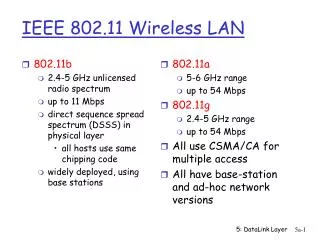
Dynamic Rate Selection (DRS) • Dynamic Rate Selection or Adaptive Rate Selection/shifting. • 802.11a, 802.11g modes: 54, 48, 36, 24, 18, 12, 9, 6 Mbps • 802.11b mode: 11, 5.5, 2, 1 Mbps • Orinoco 2X mode: 108, 96, 72, 48, 36, 24, 18, 12 Mbps
Data Rate Coverage Areas -85 dBm -76dBm -72 dBm 24 Mbps 18 Mbps 9 Mbps
Chapter-4 Topics • . Wireless Networking J. Bernardini
802.11 Open Association Process Wireless Networking J. Bernardini
Association, Reassociation, Disassociation • Covered next week Wireless Networking J. Bernardini
Regulatory Domain Requirements • Covered next week Wireless Networking J. Bernardini
Point Coordination Function (PCF) • Polling: Channel access method in which each device asked in sequence if it wants to transmit • Effectively prevents collisions • Point Coordination Function (PCF): AP serves as polling device or “point coordinator” • Point coordinator has to wait only through point coordination function IFS (PIFS) time gap • Shorter than DFIS time gap
DIFS and DCF frames • If point coordinator hears no traffic after PIFS time gap, sends out beacon frame • Field to indicate length of time that PCF (polling) will be used instead of DCF (contention) • Receiving stations must stop transmission for that amount of time • Point coordinator then sends frame to specific station, granting permission to transmit one frame • 802.11 standard allows WLAN to alternate between PCF (polling) and DCF (contention)