Download
1 / 70
770 likes | 991 Views
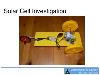
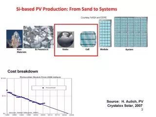
Determining the parameters of solar cell. Dr. Daniel Cotfas Transilvania University of Brasov The Physics department dtcotfas@unitbv.ro. Measurement environments. in the lab; Measurements under illumination; Measurements in the dark ; in natural light conditions;.

E N D
Determining the parameters of solar cell Dr. Daniel Cotfas Transilvania University of Brasov The Physics department dtcotfas@unitbv.ro
Measurement environments • in the lab; • Measurements under illumination; • Measurements in the dark ; • in natural light conditions;
Methodological analysis • The fitting procedure, using either the one or the two diodes model; • The Analytical Five Point Method; • The Simple Conductance Technique; • The Conductance Optimization Method; • The approximation equation and fitting procedure; • Etc…. • The methods for determining the series resistance and not only: • Method of slope at the (Voc,0) point; • The two characteristics method; • The area method; • Maximum power point method; • The simplified method of the maximum point; • Method of Quanxi Jia and Anderson; • Ideal one-dimensional Case; • Method of the two-diode solar cell model; • A static method; • The generalized area method • Etc….
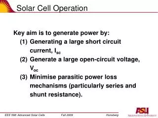
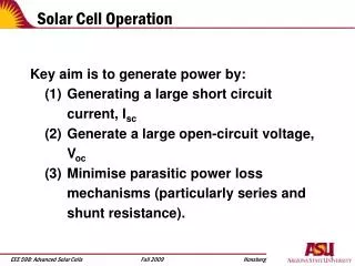
The main parameters for measuring solar cells performance • Isc-short circuit current; The short circuit current (Isc), is the current which is generated by the solar cell if it is connected to a low impedance forcing the voltage across the device to V = 0. Voc-open circuit voltage; The open circuit voltage (Voc), i.e. the voltage which builds up across the cell as long as its terminals are kept on high impedance forcing the electrical current to I = 0. This quantity is related to the bandgap of the semiconductor used. FF- fill factor; The fill factor (FF) corresponding to the ratio of the power which can need be generated by the solar cell (under maximum power conditions i.e. when it is connected to a suitable charge) to the product of Voc*Isc This factor is related to the curvature of the I-V characteristics. Cell efficiency; The cell efficiency can be determined from these three external parameters and from the area of the cell
Equivalent circuits • the static regime; • the dynamic regime (alternative)
The equivalent circuit for the CdTe cell Whereas for the silicon cells it was shown that it is useful to take into consideration the second diode as well in the model describing the currents mechanisms in the cells, in case of thin film cells (heterojunctions) this only has a small influence, which can thus be neglected (Gottschalg, 1997). But the standard one diode model cannot completely describe the CdTe(thin film) cells.
For a CdTe cell the back contact must be taken into consideration, here being formed a metal-intrinsic-semiconductor junction opposed to the main junction. This contact is manifested by two effects: the roll over effect – the I-V characteristic is saturated close to the open circuit voltage for low operating conditions; the cross over effect –I-V curves in the dark and under illumination are intersected, thus the super positioning principle being contradicted. The cell behavior is influenced by the Schottky diode only at small temperatures. As it doesn’t belong to the active junction it will only play the role of a resistance which will be added at the series resistance of the cell.
Passing from the equivalent circuit in static regime to dynamic The equivalent circuit from fig. is obtained by replacing the diode with its diffusion capacity Cd, the barrier capacity Ct and the dynamic resistance in parallel with the shunt resistance
Why about raising I-V characteristic of solar cells? The I-V characteristic is one of the most important methods of determining and studying the parameters of solar cells Comparisons Autolab Capacitor MOSFET Conclusions
Determining the solar cell parameters is important for industrial considerations as well as for scientific research. It can be performed using various methods. One of the most widely implemented is the use of the current- voltage characteristic, I-V, under illumination or in the darkness. THE I-V CHARACTERISTIC OF SOLAR CELLS
TECHNIQUES OF RAISING THE I-V CHARACTERISTIC OF SOLAR CELLS • Autolab –used as a electronic load • Capacitor • MOSFET
The electronic load • The raising of the I-V characteristic of the solar cell using the electronic load was realized with the Autolab, used on the mode “Potentiostat”. • The points (V,I) were acquisitioned using the method Cyclic voltammetry. • The number of points (V,I) measured was 990, and the duration of measurements was 30 s. The I-V characteristic for the c-Si solar cell is presented in the figure. • The advantage of this technique lies in the possibility to start the characteristic from the voltage of zero volts.
NI ELVIS setup NI ELVIS II a real “music” “from the past” to “the future” in engineering research and education ! NI Educational Laboratory Virtual Instrumentation Suite
The solar cell I-V characteristic raised with MOSFET • The raising of the I-V characteristic with the MOSFET technique was realized by using a simple circuit. • For the command of the transistor MOSFET a triangular 1 Hz signal was generated with the module Function Generator of the NI ELVIS platform. • The signals (both voltages) were measured on the channels AI0 and AI1. • The amplitude of the signal was chosen so that the transistor works on the linear portion and covers completely the cell characteristic. The MOSFET transistor plays the role of a variable resistance.
The capacitor method • The principle of this technique consists of: acquisitioning the values for the current (the voltage drop is measured on the resistor) and for the voltage on the capacitor charging cycle. • The capacitor starts to charge when the cell is connected to it. • The capacitor is charged starting from the short circuit current (Isc) until the cell reaches the open circuit voltage (Voc).
The comparison The comparison of solar cell I-V characteristics, raised with electronic load, MOSFET and capacitor • It is observed that for the MOSFET and capacitor techniques, the characteristic doesn’t start from the zero value for voltage. A part of the characteristic is thus lost. • This is due to the internal resistances of the used MOSFET and solid state relay and the resistance on which the voltage drop is measured to determine the current generated by the cell. • The smaller the resistance used for the current measurement is, the fewer points are lost from the characteristic.
The comparison • The advantages presented by the MOSFET and the capacitor techniques are: • a much smaller time to raise the characteristic in comparison to the one needed in the electronic load technique; • the large number of points (V,I) that can be acquisitioned in a very short time, facilitating a very good fitting; • the cell parameters remain constant throughout the measurement; • the cost is very low for both methods.
Conclusions • By raising the I-V characteristics on the same graph, a good matching is observed between the three characteristics. • It can be concluded that for the raising of the characteristic much cheaper devices can be used than the electronic load that have the advantage of a small duration of raising the solar cell characteristic and they can also be used for high power. • Thus, portable devices can be designed on the basis of these techniques of solar cells characterization that allow the checking of the panels or arrays at the mounting place, not necessarily in the lab. • From measurements it was observed that any resistance that is added to the circuit translates the I-V characteristic towards the left. • From this perspective, in the raising of the I-V characteristics of the solar cells, it is necessary to consider the minimizing of the supplementary resistances introduced in the circuit (the internal resistances of the components under use, the connection wires’ resistances and the contacts…)
The Analytical Five Point Method The method consists of determining the cell parameters by using: Voc, Isc, Im, Vm, Rso, Rsho
Rs0 and Rsh0 are obtained from the measured characteristic by a simple linear fit
An approximation equation • As the fitting of the I-V characteristic is more accurate and easier the less parameters must be determined, an approximate equation can be found, and it gives good results. Thus the reverse saturation current is eliminated. , where
exp(ΛVoc) х exp(-ΛVoc)=1 For short circuit condition,(I = Isc) in equation, we get V < 0 and in order to impose V = 0, a coefficient B will be added to equation
The Simple Conductance Technique It is based on the Werner method which has been adapted for solar cells and used to determine the solar cell parameters
Semi-logI-V characteristic for solar cell under dark condition
The experimental set up for I-V dark measurement • a dark chamber; • the solar cell; • Keithley Model 2420, High Current Source Meter or Autolab PGSTAT30; • data acquisition board NI 6036E; • a copper thermostat with a heater; • a sensor LM 335 for temperature measurement. • PC.
The dark I-V characteristic was raised for the multicrystalline silicon solar cell in forward bias, kept at the temperature of 200C. The characteristic was raised by using Autolab PGSTAT30 used as potentiostat. For the fitting of the dark I-V characteristic obtained the Origin software was used. In the fitting procedure, five independent parameters were used. These parameters are: I01 and I02 - reverse saturation currents, m1 and m2 - ideality factor of the diodes and Rsh – shunt resistance.
The determination of the series resistance The series resistance in a solar cell is determined by the series resistance of the base, by the resistance of the metal-semiconductor contacts at electrodes and by the resistance of the diffused layer from the illuminated surface of the cell…
The methods for determining the series resistance • Due to the major effects that the series resistance, Rs, has on the solar cell performance, a series of methods were developed to determine and reduce them. • The determining of the series resistance can be performed in darkness as well as under illumination. • Among the most widely used methods there are: a static method and a dynamic method: • the method of slope at the (Voc,0) point; • the two characteristics method; • the maximum power point method; • the area method; • the generalized area method; • the analytical five point method; • the method of Quanxi Jia and Anderson • the Cotfas method and others.
Measurements in the dark 1. A static method: Rs can be deduced as the value from the gap on the V axis, between the actual curve and the diffusion line 2. A dynamic method-using the one diode model, superposing a very low amplitude a.c. signal to a forward electric injection , the following expression is obtained for the dynamic resistance: Measurements under illumination in this case there are much more methods, in this course only few of them being reminded.
I ΔI ΔIsc V ΔV1 • Method of slope at the (Voc,0) point-at constant illumination and using the one diode model Rs is determined from the relation: The two characteristics method-is a method that uses two I-V characteristics raised at the same temperature for two illumination levels. The two characteristics are translated one from the other with the quantities ΔIsc and ΔIscRs = ΔV1
The area method-using equation we shall calculate Rs: Interface for determination of series resistance using the area method for CdTe solar cell, having an area of 1 cm2
Cotfas method • The series resistance has as an effect the translation towards the left of the I-V characteristic, and the shunt resistance has as an effect the lowering of the characteristic, (the increase of the slope in the plateau). The translation on the vertical area is given by I*Rs, and on the plateau slope by V/Rsh .
The dependence of the series resistance on irradiance This dependence is fitted with a third degree polynomial. The raise of the series resistance is rapid for small illumination levels, thus explaining the non-linear dependence of the open circuit voltage on the illumination levels.
The new method • It is observed that in the equation of the mathematical model, besides the series resistance there are other three unknown quantities. • To find the solutions of the four unknown quantities, a non linear system of four equations will be numerically solved. • The supplementary equations are obtained by putting in the circuit some resistances bound in series with the series resistance of the cell. • The values of these resistances were previously measured. • The system of non linear equations is solved by using a program realized in LabVIEW.
The new method • The effect of the resistances added upon the I-V characteristic of the solar cell (the purple curve corresponds to the cell without added resistance, the red curve is for the resistance of 50 mΩ, the green curve for the resistance of 100 mΩ, and the blue one for the resistance of 200 mΩ)
The results • The values obtained for the series resistance of the solar cell are written in Table I. As it can be observed, the values obtained by the four methods are very close.
Conclusions • A new method to determine the series resistance of the solar cell was developed. • As the values of the series resistance of the solar cell obtained with the new method are practically equal to those obtained by the already existent methods, the sustainability of the new method is proved. Moreover, the method allows a visualizing of the series resistance variation along the entire characteristic. • The measurement chain realized is a compact one, easy to use and capable to reduce the undesired resistances in the circuits. • The LabVIEW soft used is a tool that ensures the data acquisition, as well as quick and easy data processing.
Effect of a decrease in Rsh on the simulated I–V characteristics of a crystalline silicon cell
Maximum power point method IL ≈ Isc
A flash lamp method Method of the difference between the photogenerated and the short-circuit currents The simplified maximum point method