Download
1 / 19
190 likes | 352 Views
The Second A3 Foresight Workshop on Spherical Torus (ST) Tsinghua University, Beijing, China, Jan. 6-8, 2013. Development of Mach probe for the ion flow measurement in VEST. S.M. Yang , N.K. Kim, H.Y. Lee, D.H. Na , J.G . Jo, J.W. Lee, M.G Yoo , G.H . Kim, Y.S. Hwang and Yong- S u Na*.

E N D
The Second A3 Foresight Workshop on Spherical Torus (ST) Tsinghua University, Beijing, China, Jan. 6-8, 2013 Development of Mach probe for the ion flow measurement in VEST S.M. Yang, N.K. Kim, H.Y. Lee, D.H. Na, J.G. Jo, J.W. Lee, M.G Yoo, G.H. Kim, Y.S. Hwang and Yong-Su Na* *Corresponding author’s E-mail: ysna@snu.ac.kr Department of Nuclear Engineering, Seoul National University, Seoul, Korea
Contents Motivation Introduction Basic test for the diagnosis- Circuit test- Area calibration Flow measurement at the linear device with B field curvature Future design Summary Seoul National University Fusion and Plasma Application Laboratory
Motivation– Toroidal rotation at the effect of the edge • Toroidal rotation is found to have an impact on global energy or particle confinement. • Toroidal rotation is beneficial on transport and MHD instability in tokamak plasmas.ex) suppression of turbulence, stabilization of the resistive wall mode • The core momentum transport is not fully understood and it is known that the core rotation is heavily influenced from the flux at the edge. • Rotation at the edge can be one of the important factors to understand the toroidal rotation • Measure ion velocity at the edge of the VEST Seoul National University Fusion and Plasma Application Laboratory
Motivation- Diagnosis for the ion flow • There are mainly 3 diagnostics to measure the ion flow. • Among these, Mach probe can be the best choice for the ion flow measurement at the edge of the VEST, which has relatively low temperature and density. Seoul National University Fusion and Plasma Application Laboratory
Introduction - What is the Mach Probe? • Measures the ion saturation current with 2 tips. Plasma Flow Direction [E Ko at el., PPCF ’06] • If there’s any ion flow, ion saturation current at each tip has to be identical. • In most theoretical models, flow is estimated by taking the ratio ofion saturation currents : • = • : Calibration factor Seoul National University Fusion and Plasma Application Laboratory
Introduction - Mach probe and DAQ circuit part Mach probe part DAQ circuit part • Get the ion saturation current from a plasmaand transmit the signal to the circuit. • - Vacuum seal • - Area calibration • Convert the current signal to • the voltage and send it to • the oscilloscope. • - Circuit test Tip: Receive signal BNC cable DAQ circuit gnd BNC cable Seoul National University Fusion and Plasma Application Laboratory
Experimental Setup for Circuit Test Input Signal Square wave 1kHz Vsig= 0 - 2 V • Check the circuit with increasing the voltage level. • Compare the voltage level between the 2 circuits Seoul National University Fusion and Plasma Application Laboratory
Basic test for the diagnosis - Circuit test & result • Since Mach probe compares the ion saturation current between two tips, the voltage measured by a circuit using reference voltage has to be identical. • Both circuits gave almost same voltage. Circuit 1 and 2 are identical Seoul National University Fusion and Plasma Application Laboratory
Basic test for the diagnosis - Design of Mach probe • Cylindricaltungsten tips are chosen since the geometrical effect of probe tips are known to be small in weakly magnetized plasma. • Probe lengths are smaller than ion-neutral collision length and larger than Debye length.(Probe area = , expected ion saturation current = 30mA) • To measure the parallel flow(which supposed to have higher velocity) tip direction is fixed as follows [T. Shikama at el., JNM ’06] Ceramic insulator (ceramic paste) Probe 1 (downstream) Probe 2 (upstream) B field Ceramic insulator (ceramic paste) tip Ceramic tube [In plasma] [Top view] Seoul National University Fusion and Plasma Application Laboratory
Experimental setup- Area calibration (DC plasma) Permanent magnet arrays forming cusp N S Mach Probe N W-Th Filaments Field-free & Uniform Density Plasma Region - 60 V • Hot filaments generate electrons in random direction, consider this doesn’t have any ion flow. • Ion saturation current in the two tips need to be same if the area of those are same. Seoul National University Fusion and Plasma Application Laboratory
Basic test for the diagnosis - Area Calibration -60 V (ion dominant region) Source characteristic: 60 eV electron Ion dominant region (‘Area effect on ion current’ only) Perturbation of ceramic paste on tip (not uniformly distributed) + Response of the fast electrons Area ratio S1/S2 : 1.13 • The current ratio is not unity. • Area ratio could be determined: = 1.13:1 • Biasing voltage in this source << - 60 V (negative bias) Seoul National University Fusion and Plasma Application Laboratory
Measurement at linear device with B field curvature • B field in VEST and linear device with B field curvature are similar. • Parameters at the edge of VEST and linear device with B field curvature are not significantly different. • As a preliminary diagnosis of the Mach probe at the edge of the VEST,measurement at the linear device with a B field curvature is done. Seoul National University Fusion and Plasma Application Laboratory
Experimental setup- for linear device (ECH plasma) Probe location Te ~ 8 eV ne ~ 2 x 10¹⁷m-3 B ~ 0.0875 T Operation pressure ~ 4 x 10⁻⁴ Torr, H2 (base 4 x 10⁻⁶Torr) ECH Microwave Source 300W B-field direction Flow direction [11 cm] [ECH Resonance region] Mach Probe Magnetic field coils forming resonance B field with curvature Seoul National University Fusion and Plasma Application Laboratory
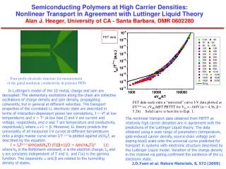
Measurement at linear device with B field curvature – Result ** Area ratio was considered Ion dominant region (Area effect only) Ceramic paste perturbed the tip. (not uniformly distributed) Electron response is applied Current Ratio ~ 0.8 • Linear device generally has M ~ 0.3 (, Ar) • Considering the area difference =1.13:1, • According to Chung’s theory, K ~ 1.6, M ~ 0.2 [K. Nagaoka, et al J. Phys. Soc.Jpn. 70, 131, 2001] [Chung, Hutchinson et al., PRA ’88] Seoul National University Fusion and Plasma Application Laboratory
Discussion for the future design • Since M ~ 0.2 is measured at linear device with magnetic field curvature,we expect to have similar ion flow at the edge of VEST. • For the measurement with a better precision, new ceramic design (Alumina) is considered as in the below figure.- Less area difference for each tip- Uniform ceramic thickness will preserve uniform sheath for eachthe probe.- Two probes can be located in parallel (angle accuracy). [ceramic for the tips] Seoul National University Fusion and Plasma Application Laboratory
Future design- Probe design for VEST Wilson type Vacuum seal [30cm] Ceramic tube [40cm] ¼” sus tube [Core measurement] [Edge measurement] • A Wilson type vacuum seal is used for the radial scan. • Length of the probe is determined for the measurement at the core for the future. Seoul National University Fusion and Plasma Application Laboratory
Summary • For the measurement of ion flow at the edge of the VEST, the Mach probe is selected for the low density & temperature plasma. • Basic test for the Mach probe is done.- Circuit test- Area calibration • As a preliminary measurement, the flow at the linear device with B field curvature is measured which expect to have similar parameters as in the edge of the VEST. • The future design for ceramics for the tip is made.- Less area difference for each tip- Uniform ceramic thickness will preserve uniform sheath for each probe.- Two probes can be located in parallel (angle accuracy). • To do a radial scan, vacuum type(Wilson seal) is decided with a sufficient length. Seoul National University Fusion and Plasma Application Laboratory
Back up- Mach probe models [Chung., PSST ’12] • Model by Mott-Smith(1926) and Hudis(1970) is older than other models • Other unmagnetized modelranged 1.0~1.34 • K can be lower than this model since strong magnetic field condition is not achieved. • But, tendency can be seen since exponential form is still conserved. Seoul National University Fusion and Plasma Application Laboratory
Back up- Design of the probe tips • The length between two probes considered to be have a small effect by experimentally comparing double sided Langmuir probe and Mach probe. • Tungsten tip can endure high temperature. • Debye length~ , ion neutral collision length >> mm (too low ). • Geometrical effect is explained with comparing MP, DLP and SP with different ion collection angle. ( respectively) • Expected ion saturation current is estimated by Bohmflux, • = 40mA • (Assuming [L Okuz et al., PSST ’04] Seoul National University Fusion and Plasma Application Laboratory