Download

1 / 31
310 likes | 425 Views
Lecture 13 Instruction Execution Pipeline. Lecture 13: Instruction Execution Pipeline. In this lecture, we will study Principle of pipeline Characteristics of pipeline Number of pipeline stages and the performance Delays of pipeline stages and the performance

E N D
Lecture 13Instruction Execution Pipeline Instruction Execution Pipeline
Lecture 13: Instruction Execution Pipeline In this lecture, we will study • Principle of pipeline • Characteristics of pipeline • Number of pipeline stages and the performance • Delays of pipeline stages and the performance • Instruction execution steps in RISC-S • 5-stage instruction execution pipeline for RISC-S • Ideal pipeline • Hazards • Improving RISC-S pipeline for hazards Instruction Execution Pipeline
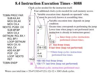
0 1 2 3 4 5 6 7 8 9 10 11 12 time Car Wash Station Car wash stations [1] S(Spray water) [2] W(Wash with detergent and brush) [3] R(Rinse) [4] B(Blow dry) Each stage takes 1 minute(identical delay) 1st car S W R B 2nd car S W R B 3rd car S W R B . . . . . . • To improve the profit • Improve the speed of the wash stations - expensive solution • Improve the throughput - Parallel wash stations - expensive solution • Improve the effective wash time - Pipeline - a less expensive solution Instruction Execution Pipeline
0 1 2 3 4 5 6 7 8 9 10 11 12 time 1st car S W R B 2nd car S W R B 3rd car S W R B . . . . . . 0 1 2 3 4 5 6 7 8 9 10 11 12 time Completion 0 1 2 3 4 5 6 7 8 9 10 11 12 time Pipeline Principle Ordinary car wash station 1 car/4 min Parallel car wash station 1st car S W R B 2nd car S W R B 3rd car S W R B 4th car S W R B 5th car S W R B . . . . . . 4 cars/4 mins Pipeline car wash station 1st car S W R B 2nd car S W R B 3rd car S W R B 1 car/1 min 4th car S W R B 5th car S W R B . . . . . . Instruction Execution Pipeline
Pipeline Terminology • Pipeline Stage • Pipeline consists of a finite number of Pipeline Stages • Pipeline Cycle • Delay of a pipeline stage is called Pipeline Cycle • Delays of the pipeline stages are not necessarily identical in practice • Control is complicated • Pipeline cycle can be made equal to the longest pipeline stage delay by sacrificing performance(pipeline cycle time) • Pipeline Latency • Time from beginning of a task to the completion of the task • Ideal Pipeline • Delays of the Pipeline Stages are identical - Pipeline Cycle • All the pipeline stages are occupied with tasks to be executed • Simple to control and provides the best performance • 1 instruction/cycle Instruction Execution Pipeline
t S0 draining S1 S2 filling Completion Stage S3 Pipeline Characteristics Assuming that there are plenty of tasks(instructions) to be executed; • All of the pipeline stages are busy most of time • Pipeline Filling • At the initial phase of the execution, pipeline stages are not fully occupied with tasks • For an n-stage pipeline, first (n-1) pipeline cycles are filling time • Pipeline Draining • At the final phase of the execution, pipeline stages are not fully occupied with tasks • For an n-stage pipeline, last (n-1) pipeline stages are draining time I0 I1 I2 I3 I4 I5 I6 I7 . . . In-1 In I0 I1 I2 I3 I4 I5 I6 . . . In-2 In-1 In I0 I1 I2 I3 I4 I5 . . . In-3 In-2 In-1 In I0 I1 I2 I3 I4 . . . In-4 In-3 In-2 In-1 In Instruction Execution Pipeline
0 1 2 3 4 5 6 7 8 9 time 1st car S W R B 2nd car S W R B 3rd car S W R B 4th car S W R B 5th car S W R B Completion = 8 minutes 0 2 4 6 8 10 12 time 1st car SW RB 2nd car SW RB Completion = 12 minutes 3rd car SW RB 4th car SW RB 5th car SW RB Number of Pipeline Stage Comparison of car wash stations with 4-stage(S,W,R,B) and 2-stage(SW,RB) pipeline, identical pipeline latency(4 minutes) • 4-stage pipeline with 1 minute pipeline cycle • 2-stage pipeline with 2 minute pipeline cycle The more pipeline stages, the better performance Instruction Execution Pipeline
0 1 2 3 4 5 6 7 8 9 time 1st car S W R B 2nd car S W R B 3rd car S W R B 4th car S W R B 5th car S W R B Completion = 8 minutes 0 1 2 3 4 5 6 7 8 9 10 time 1st car S W R B 2nd car S W R B 3rd car S W R B 4th car S W R B Completion = 10 minutes 5th car S W R B Delay of Pipeline Stages Comparison of 4-stage car wash stations with different pipeline stage delays • Identically 1 minute delay Identical pipeline stage delay shows better performance • S(0.5 min) - W(1.5 min) - R(0.5 min) - B(1.5 min) pipeline Instruction Execution Pipeline
ADD SLL LD JMP MAR PC, R; MAR PC, R; MAR PC, R; MAR PC, R; IF PC PC + 4; PC PC + 4; PC PC + 4; PC PC + 4; IR MBR; IR MBR; IR MBR; IR MBR Decode; Decode; Decode; Decode; DR Read Rs1 and S2; Read Rs1; Read Rs1 and S2; Read Rs1 and S2; Do Rs1 + Rs2; Do shl Rs1; Do Rs1 + S2 for addr; Do Rs1+S2 for addr, A T/F(test condition), T:store addr into PC; Store addr into MAR, R; M Store into Rd; Store into Rd; Store MBR into Rd; SR Instruction Execution Steps Instruction Execution Pipeline
A/M Buffer M/S Buffer D/A Buffer I/D Buffer IF DR A M SR Instruction Execution Pipeline:RISC-S A 5-stage pipeline • IF-DR-A-M-SR pipeline • For the instruction execution pipeline, information have to be passed to the succeeding pipeline stage • Need Inter-stage buffers made of latches • I/D buffer, D/A buffer, A/M buffer, M/S buffer Instruction Execution Pipeline
IR M[PC] NPC PC + 4 I/D Buffer IF Stage +4 NPC PC M IR IF Stage Instruction Fetch and update PC stage Instruction Execution Pipeline
I/D Buffer DR Stage D/A Buffer NPC NPC A Rs1 B Registers S2 Rs2 D imm13 Sign Expander imm32 IR C cc t OP DR Stage Instruction decoding and register read stage OP <- OP-code A(Rs1) <- R[IR14..18] t <- IR13 B(Rs2) <- R[IR0..4] D(S2) <- (IR12)19#IR0..12 C(Cond) <- IR19..22 cc(SCC) <- IR24 (NPC <- NPC) Instruction Execution Pipeline
A Stage A/M Buffer D/A Buffer NPC NPC addr =0? MUX T Flag A ALU B AO COND MUX D imm32 B C Flag set C cc Rd t OP OP A Stage ALU operations using operands, and effective address computation, and condition test for conditional branches Memory Ref Instr(t=1): AO <- NPC+D(imm32) LD Instruction: C <- C Functional instr(t=0): AO <- A op B C <- C Control instr: AO <- NPC+D(imm32) T <- (flag(C) op 0) (OP <- OP) (NPC <- NPC) Instruction Execution Pipeline
M Stage M/S Buffer A/M Buffer NPC MUX PC T DATA AO Addr Operation Result Memory AO B data C C Rd OP OP M Stage Memory access for read and write, and decide final PC value for branch instructions LD: DATA <- M[AO] ST: M[AO] <- B Functional instruction: AO <- AO Branch instruction: if T=0 PC <- AO if T=1 PC <- NPC (OP <- OP) (C <- C) Instruction Execution Pipeline
SR Stage M/S Buffer DATA data MUX Register data AO address C OP SR Stage Store the result of operation in a register for a functional instruction, and store the data read from memory to a register for load instruction Functional instruction: R[C] <- AO LD: R[C] <- DATA Instruction Execution Pipeline
Time Out • 남편은 캘리포니아 주의 사막에 가서 군사훈련을 받게 되었다. • 남편은 집으로 이런 내용의 편지를 보냈다. “지금 나에게 생각나는 것은 당신이 무척 보고 싶다는 것과 발이 몹시 시리다는 것뿐이오. 밤을 좀더 편안히 보낼 수 있도록 당신이 뭔가 보내줬으면 좋겠소.” • 부인은 남편의 사기를 북돋워주기 위해서 속살이 훤히 들여다보이는 잠옷을 입고 찍은 사진 한 장을 보냈다. • 2 주일 후 이런 답장이 왔다. “여보, 당신 참 멋있어! 그런데, 이 번에는 순모 양말 몇 켤레 보내줄 수 있겠소?” Instruction Execution Pipeline
Ideal Pipeline Ideal Pipeline • Delays of the pipeline stages are identical - Pipeline Cycle • All the pipeline stages are occupied with tasks, except the filling time and draining time • Complete one task for every pipeline cycle after the filling time Reasons for preventing pipelines from operating as an ideal pipeline even though delays of the pipeline stages are identical • Hazards • Structural Hazard • Data Hazard • Control Hazard Instruction Execution Pipeline
0 1 2 3 4 5 6 7 8 1st car S W R B 2nd car S W R B Structural Hazard Cases when Structural Hazards take place • More than one instruction require the same pipeline stage at the same clock cycle • This never happens when the delay of the pipeline stages are identical • More than one pipeline stages try to use the same hardware resource at the same clock cycle • IF and A stages: Operation with Adder • DR and SR stages: Access register file • IF and M stages: Access memory Instruction Execution Pipeline
LD IF DR A M SR ADD IF DR A M SR LD IF DR A M SR ADD IF DR A M SR IF DR A M SR IF DR A M SR IF DR IF Stall Cycle LD IF DR A M SR ADD IF DR A M SR LD IF DR A M SR ADD IF DR A M SR IF DR A M SR IF DR A M SR IF DR A M SR IF DR A LD IF DR A M SR ADD IF DR A M SR LD IF DR A M SR ADD IF DR A M SR IF DR A M SR IF DR A M SR IF DR A M SR IF DR A Example: Structural Hazard • Structural Hazard due to Adder - IF and A stage in the same cycle • Structural Hazard due to Register • Structural Hazard due to Memory Instruction Execution Pipeline
Clock Cycle R R Store R Read R Hardware Solution - For Structural Hazards - • Adder Hazard in IF and A stages • Include a simple +4 adder in the IF stage to avoid using ALU in A stage in calculating PC+4 • Register Hazard • Register can be made to write access in the first half of the clock cycle, and read access in the second half of the clock cycle • Memory Hazard • Dedicated memory, i.e., separate Instruction Memory and Data Memory • 2-port memory Instruction Execution Pipeline
Not a hazard Hazard Data Hazard Data Hazard is possible when more than one instruction in a sequence share the same data SLL R5, R1 IF DR A M SR ADD R1, R2, R3 IF DR A M SR AND R1, R4, R4 IF DR A M SR SUB R5, R1, R6 IF DR A M SR XOR R1, R7, R8 IF DR A M SR • Read After Write(RAW) Hazard • Supposed to read the written data, but reading it takes place first • Write After Read(WAR) Hazard • Supposed to read first then write it, but writing it takes place first • Write After Write(WAW) Hazard • Written data at the same location in a wrong order Instruction Execution Pipeline
IF DR A M SR IF DR A M SR IF DR A M SR IF DR A M SR Data Hazards RAW Hazard Ii precedes Ij, and Ij tries to read a register or data memory location before Ii stores data into there. ADD R2, R3, R1 AND R1, R4, R4 • WAR Hazard • Iiprecedes Ij, and Ii reads data and Ij writes data at the same location and writing take place earlier than reading • This never happens if all the instructions go through the same pipeline stages with same delay because instructions go through SR stage(for writing) later than DR stage(for reading) • WAW Hazard • Ii precedes Ij, and both Ii and Ij writes data at the same location, but in a wrong order • This never happens also if the assumption in WAR is true Instruction Execution Pipeline
D/A Buffer A Stage M Stage A/M Buffer M/S Buffer MUX DATA AO Memory ALU AO MUX t Forwarding Circuit: For RAW Data Hazard Circuit that forwards the data to be stored in SR stage to ALU input MUX in A stage Data to be stored in a register in SR stage; DATA, AO in M/S Buffer AO in A/M Buffer These values in inter-stage buffers are forwarded to the ALU input MUX Instruction Execution Pipeline
Instruction Scheduling with Forwarding Circuit Resolving Data Hazard with registers by forwarding : No delay SLL R5, R1 IF DR A M SR ADD R1, R2, R3 IF DR A M SR AND R1, R4, R4 IF DR A M SR SUB R5, R1, R6 IF DR A M SR XOR R1, R7, R8 IF DR A M SR Instruction Execution Pipeline
Represents forwarding Load Delay Due To RAW:Improvement by Forwarding Circuit • Load Delay: 2 cycles LD R1, X IF DR A M SR stall stall ADD R1, R2, R3 IF DR A M SR AND R1, R4, R4 IF DR A M SR SUB R5, R1, R6 IF DR A M SR XOR R1, R7, R8 IF DR A M SR • Load delay with forwarding: 1 cycle • LD R1, X IF DR A M SR • stall • ADD R1, R2, R3 IF DR A M SR • AND R1, R4, R4 IF DR A M SR • SUB R5, R1, R6 IF DR A M SR • XOR R1, R7, R8 IF DR A M SR Instruction Execution Pipeline
Represents forwarding Load Delay Due To RAW:Improvement by Software Scheduling LD R1, X IF DR A M SR stall ADD R1, R2, R3 IF DR A M SR SUB R1, R5, R4 IF DR A M SR LD R6, Y IF DR A M SR Software Scheduling LD R1, X IF DR A M SR LD R6, Y IF DR A M SR ADD R1, R2, R3 IF DR A M SR SUB R1, R5, R4 IF DR A M SR Instruction Execution Pipeline
Control Hazard • Address of the instruction after a branch instruction is determined in M stage. Therefore, the next instruction fetch must be delayed until the branch instruction completes in M stage. ADD R1, R2, R3 IF DR A M SR JMP COND, X IF DR A M SR stall stall stall next instruction IF DR A M SR • Branch Delay of 3 cycles • Value of PC is decided by the value of T, which select the from input addresses to the MUX in M stage - AO(branch address) or NPC(PC) • Value of T is decided by testing the conditions in A stage • Branch address can be decided earlier if branch condition can be tested earlier Instruction Execution Pipeline
D/A Buffer I/D Buffer DR Stage MUX PC =0? NPC Flag Address Adder Registers Sign Extender Reduction of Branch Effect If calculation of Branch Address and Testing Condition are made earlier, Branch delay can be reduced. Move these operations to DR stage; • Include an Adder for branch address calculation in DR stage • Move Circuit to test the branch condition in M stage to DR stage Instruction Execution Pipeline
Branch Delay:Improvement by Software Rescheduling ADD R1, R2, R3 IF DR A M SR JMP COND, X IF DR A M SR stall next instruction IF DR A M SR Branch Delay: 1 cycle Rescheduling JMP COND, X IF DR A M SR ADD R1, R2, R3 IF DR A M SR next instruction IF DR A M SR This is possible only if COND is set by the instruction before the JMP instruction. Conditional branch on the COND set by the ADD(following JMP) is not possible. No branch delay Instruction Execution Pipeline
Prediction Actual execution Branch Delay:Improvement by Hardware Branch Predictor Predict TAKEN, and actually NOT TAKEN IF DR A M SR IF DR A M SR IF DR A M SR IF DR A M SR IF Predict TAKEN, and actually TAKEN ADD R1, R2, R3 IF DR A M SR JMP COND, X IF DR A M SR LD R1, Y SUB R3, R4, R5 … X ADD R1, R6, R5 IF DR A M SR 1 Cycle Delay 1 Cycle Delay Predict NOT TAKEN, and actually TAKEN ADD R1, R2, R3 IF DR A M SR JMP COND, X IF DR A M SR LD R1, Y IF SUB R3, R4, R5 … X ADD R1, R6, R5 IF DR A M SR Predict NOT TAKEN, and actually NOT TAKEN IF DR A M SR IF DR A M SR IF DR A M SR IF DR A M SR 1 Cycle Delay No Delay Instruction Execution Pipeline
Branch Number of Branch Delay cycles Prediction Actually TAKE Actually NOT TAKEN TAKEN 1 1 NOT TAKEN 1 0 Branch Prediction Penalty Instruction Execution Pipeline