Download
1 / 26
260 likes | 446 Views
ALICE High Level Trigger. The ALICE High-Level-Trigger. Overview. The ALICE High-Level-Trigger: dataflow in the ALICE experiment trigger systems : L0, L1, L2 TPC – largest datasource High-Level-Trigger: Tasks & Implementation The HLT ReadOut-Receiver-Card (H-RORC): Tasks & Requirements

E N D
ALICE High Level Trigger The ALICE High-Level-Trigger Torsten Alt - KIP Heidelberg IRTG 28/02/2007
Overview The ALICE High-Level-Trigger: dataflow in the ALICE experiment trigger systems : L0, L1, L2 TPC – largest datasource High-Level-Trigger: Tasks & Implementation The HLT ReadOut-Receiver-Card (H-RORC): Tasks & Requirements Implementation Torsten Alt - KIP Heidelberg IRTG 28/02/2007
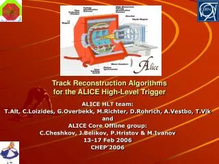
The ALICE detector ITS : Inner Tracking System TPC : Time Projection Chamber TRD : Transition Radiation Detector Torsten Alt - KIP Heidelberg IRTG 28/02/2007
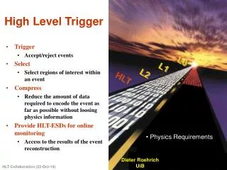
Trigger L0 - 1.2µs : event occured L1 – 6.5µs : start sampling in the Front-End-Electronics L2 – 88µs : readout data from the Front-End-Electronics data buffer L0, L1, L2 look for „valid“ events and trigger the readout! Torsten Alt - KIP Heidelberg IRTG 28/02/2007
High-Level-Trigger : HLT Needs for a High-Level-Trigger: the sub-detectors produce more data than a permanent tape storage system can handle Online analysis allows to trigger for rare events i.e. jets Events can be „tagged“ to prepare them for later offline analysis Torsten Alt - KIP Heidelberg IRTG 28/02/2007
HLT - Dataflow TRD ITS DiMuon TPC HLT Permanent Storage Torsten Alt - KIP Heidelberg IRTG 28/02/2007
HLT - Dataflow TRD ITS DiMuon TPC IN: 16 GB/s HLT OUT: < 1,2 GB/s Permanent Storage Torsten Alt - KIP Heidelberg IRTG 28/02/2007
Picture of the ALICE TPC Sector P.Glaessel – will be replaced by ITS later Torsten Alt - KIP Heidelberg IRTG 28/02/2007
Event in the STAR TPC Torsten Alt - KIP Heidelberg IRTG 28/02/2007
TPC Read-Out Electronics pad OROC row IROC • 2 x 18 sectors ( Side A & C) • 6 readout partitions (patch) per sector : 216 patches • ~ 26 rows per patch • ~ 90 pads per row • = 557,568 pads Torsten Alt - KIP Heidelberg IRTG 28/02/2007
HLT Infrastructure for one TPC sector TPC sector Front-End Processors HLT - cluster FEP BDW H-RORC RP CF reconstrcution data flow H-RORC RP CF display data flow BDW FEP BDW H-RORC RP CF TR H-RORC RP CF TDS BDW HLT Online Display FEP BDW RP CF H-RORC H-RORC RP CF BDW DAQ second sector Torsten Alt - KIP Heidelberg IRTG 28/02/2007
Tracking in the HLT Raw Data(Ordering, Zero Suppression) - Data amount + Computing amount Cluster Finding (in readout partition) Can be done in the FPGA Tracking (Conformal-Mapping / Track Follower) Torsten Alt - KIP Heidelberg IRTG 28/02/2007
Clusterfinding 1 Torsten Alt - KIP Heidelberg IRTG 28/02/2007
Clusterfinding 2 Torsten Alt - KIP Heidelberg IRTG 28/02/2007
HLT in the pit – Counting Room 2 &3 CR 2 & 3 : HLT Beampipe ALICE Torsten Alt - KIP Heidelberg IRTG 28/02/2007
The HLT Cluster • First Stage : • Installation will take place from 28.2 to 7.3. • 80 server with 2 x DualCore Opteron • Each server will be equipped with 2 RORCs • Each server will be equipped with a remote • control system : CHARM • 216 incoming DDLs for the TPC • 10 outgoing DDLs to the DAQ HLT Prototype at KIP Torsten Alt - KIP Heidelberg IRTG 28/02/2007
The H-RORC Torsten Alt - KIP Heidelberg IRTG 28/02/2007
H-RORC Block diagramm Memory Configuration DDR-SD DDR-SD USER- FLASH XC95144 CPLD CMC-J11/J22 DDR-SD CFG- FLASH DDR-SD CMC-Connector CMC-Connector OSC Serial links XILINX VIRTEX4 LX40 RS-232 PLATFORM PROM ETH-PHY LVDS links Power 1V2 POWER Power 1V8 TAGNET OSC TAGNET Power 2V5 PCI-66/64 PCI-Power 3V3 Torsten Alt - KIP Heidelberg IRTG 28/02/2007
H-RORC Overview • H-RORC : HLT Read-Out Receiver Card • Tasks: • Receiving of the raw detector data • Injecting the data into the main memory of the hosts of the HLT framework • Online processing of the data in hardware • Sending processed data out of the HLT • Serve as a developing platform for new designs • Requirements : • - Flexible and modulare architecure • - Possibility to upgrade to larger FPGAs • - Safe update of the firmware Torsten Alt - KIP Heidelberg IRTG 28/02/2007
Clusterfinding in the FPGA 1 • Each datapoint is represented by 4-dimensional vector (row, pad, time, charge) • Processing can by done for each row independently: Clusterfinding is a parallel process • Clusterfinder operates on (pad, time, charge) • Main operations: add, multiply, compare, store • Main operations can be done in parallel Torsten Alt - KIP Heidelberg IRTG 28/02/2007
Clusterfinding in the FPGA 2 • 1.stage: CF-DECODER CF calculate the weighted time, the sequential charge and the total charge. • 2.stage: CF-MERGER The values are compared and merged if they correspond • 3.stage: DATA-MERGER The clusters are written to a memory Time Pad Add & Multiply Compare & Add Store RAW Decoder Merger Data-Merger Clusterfinder Torsten Alt - KIP Heidelberg IRTG 28/02/2007
Secure Configuration Memory Configuration DDR-SD DDR-SD USER- FLASH XC95144 CPLD CMC-J11/J22 DDR-SD CFG- FLASH DDR-SD CMC-Connector CMC-Connector OSC Serial links XILINX VIRTEX4 LX40 RS-232 PLATFORM PROM ETH-PHY LVDS links Power 1V2 POWER Power 1V8 TAGNET OSC TAGNET Power 2V5 PCI-66/64 PCI-Power 3V3 Torsten Alt - KIP Heidelberg IRTG 28/02/2007
Secure Configuration 2 FLASH CPLD USER 2 Virtex4 FPGA USER 1 Write SecureConf PCI A user configuration can be written to the FLASH via PCI. Depending on the size of the FLASH several user configurations can be stored. Torsten Alt - KIP Heidelberg IRTG 28/02/2007
Secure Configuration 3 FLASH CPLD CTRL/STATUS CTRL USER 2 Virtex4 FPGA USER 1 Configuration data SecureConf PCI The CPLD checks the FLASH for a valid user configuration and the FPGA is then configured with this configuration Torsten Alt - KIP Heidelberg IRTG 28/02/2007
Secure Configuration 4 FLASH CPLD USER 2 WATCHDOG Virtex4 FPGA USER 1 SecureConf PCI After configuration a watchdog is enabled inside the CPLD. It needs to be disabled by a defined sequence send via PCI. If anything goes wrong and the watchdog isn`t disabled, it will time out and the FPGA will be reconfigured with the SecureConf. Torsten Alt - KIP Heidelberg IRTG 28/02/2007
Secure Configuration 5 FLASH CPLD CTRL/STATUS CTRL USER 2 WATCHDOG Virtex4 FPGA USER 1 SecureConf Configuration data PCI The watchdog has timed out and the FPGA is reconfigured with the SecureConf. The SecureConf contains a design which will always give access to the FLASH via PCI. Torsten Alt - KIP Heidelberg IRTG 28/02/2007