Download
1 / 29
290 likes | 392 Views
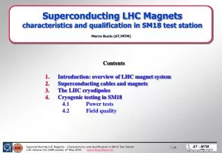
Contents Introduction: overview of LHC magnet system Superconducting cables and magnets The LHC cryodipoles Cryogenic testing in SM18 4.1 Power tests 4.2 Field quality. Superconducting LHC Magnets characteristics and qualification in SM18 test station. Marco Buzio (AT/MTM).

E N D
Contents Introduction: overview of LHC magnet system Superconducting cables and magnets The LHC cryodipoles Cryogenic testing in SM18 4.1 Power tests 4.2 Field quality Superconducting LHC Magnets characteristics and qualification in SM18 test station Marco Buzio (AT/MTM)
Acknowledgements This talk gives some highlights on the work done by many people in the AT and TS department over many years. Special thanks to: L Bottura, V Chohan, A Masi, JG Perez, P Pugnat, S Sanfilippo, A Siemko, N Smirnov, W Venturini Delsolaro (AT/MTM) M Pojer, L Rossi, D Tommasini (AT/MAS) J Axensalva,JP Lamboy,B Vuillerme, L Herblin (AT/ACR)
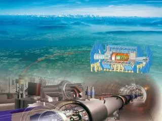
Overview of the LHC Magnet System Cryodipoles in SMA18 • Magnet lattice = ½ cost of LHC, 10 yr R&D • Challenge: large-scale, advanced technology transfer to industriesextensive tests needed at CERN (~10% of magnet cost) Short Straight Section in SM18 Different types of correctors
Status • Baseline includes cold tests for all main magnets, details to be finalized • 1 octant of dipole cold masses delivered, ~120 cold tested (only two rejected) • 6 Short Straight Sections assembled and tested • cold test rate expected to ramp up from 8 to 14 magnets/week as soon as all 12 benches completed (Q3 2004) • first dipole installation tests foreseen in June • End of cold test phase expected Q3 2006.
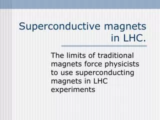
Superconducting vs. resistive: field quality Field quality determined by iron pole shaping geometry accessible for direct measurements Measurement/shimming can be iterated large conductor positioning errors tolerable Field depends on the homogeneity of material magnetic properties Field quality determined by coil geometry geometry not accessible for direct measurements at working temperature (cryostat/beam pipe) results must be extrapolated coils must be shimmed during production, errors extremely difficult to correct conductor positioning errors of ~ 25 mm provoke relative field errors ~ 10-4
J T B Stability of superconductor: quenches • A quench is a sudden thermodynamic transition to the normal resistive state, as the material crosses the critical surface Bcr(Jcr,T) • Superconducting wire is intrinsically unstable: a quench can be triggered locally by the deposition of a few mJ (very low heat capacities at 1.9K !), which may be released by: - cable movements (few mm) magnetic friction, Lorentz forces, mechanical friction - cracking of resin - radiation from the beam • Quench stability is achieved by making the SC into thin filaments embedded in a conductive matrix. • The performance of a magnet is degraded w.r.t. material properties due to manufacturing process, non-uniform field and current distributions • Quench detection and active magnet protection are necessary to avoid excessive localized heat deposition (global margin for LHC dipoles ~ 85%) Critical surface of NbTi
15 mm LHC superconducting cable • Total: 400 tons NbTi, 7000 km • Rutherford type structure • 28 or 36 strands per cable, twisted to minimize linked flux during field ramps • up to 8800 7 mm Ø filaments per strand, embedded in Cu to achieve thermal stability(minimize Joule heating + maximize heat transfer after a quench) • SC cross-section as high as 60% of the total to increase current density relatively low stability • insulated with barber-pole wrapped polymide to allow for high LHe penetration (90% filling factor) • keystoned + a different design for each coil layer (to allow current grading) Cu NbTi
LHC superconducting cable One LHC superconducting cable carries up to 13000 A ….. … which is equivalent to about 10 conventional power lines … … or this thick bunch of resistive copper cables.
Cryodipole: overview Instrumentation connector
Dipole coils Cu spacer blocks Beam pipe Quench Heaters (outer) ideal cos(q) current distributionover a circular profile giving anuniform field inside the circle … NbTi cable Quench Heaters (inner) … and the optimized approximationmaking use of a discrete conductor Outer layer (lower B, higher J) Inner layer (higher B, lower J)
1.70 MN/m 0.75 MN/m 125 kN/coil Total current 1 MA Lorentz forces • Magnetic coils tend to expand under the effect of self-forces • Coils in the two apertures are attracted • Stress levels depend on field strength, thermal contraction, level of pre-compression and width of any gaps
Energy stored The total energy stored in the magnetic field of each dipole is = 7 MJ … … that is equivalent to the mechanical energy necessary to lift a massof 32 tons to the height of 22 m … … or the thermal energy sufficient to melt 5 kg of steel … … or the electrical energy needed to light a 100W bulb for 20 hours … … or the chemical energy contained in about 500 gr of delicious Swiss muesli ! However … WARNING: electrical insulation can be irreversibly damaged by sparks containing less than a J !!
Dipole cold mass Austenitic (non-magnetic) steel collars Shrinking cylinder (welded under compressionto confer curved shape) Alignment pins Beam pipe + kapton insulation 20K GHe cooling conduit Corrector spool pieces Pseudo-random cryopumping holes “Lyre”-shaped current leads Beam screen
Two-in-one concept • Part of the magnetic flux returning through the yoke goes to enhance the field in the other aperture (+10%) Magnetic symmetry is broken Field errors are coupled collars iron yoke • Number of magnets to build is halved Space occupied in the tunnel is considerably reduced Difficulty, cost and risk of construction are increased Overall: higher cost effectiveness • Distance and parallelism of the two beam rings are guaranteed Construction errors cannot be corrected tighter tolerances
Magnet test sequence (essential steps) • SM18/SMI2 • Warm HV insulation- Fiducialization (geometry)- Special magnetic measurements(polarity, field direction)- Inserion of beam screen- Preparation for storage • SM18 • Cold HV insulation - Quench protection system- Training- Magnetic measurements- Special tests (short sample limit, geometry …) • SMA18 • Electrical & leak tests- Instrumentation setup- Cryostating- Preparation for cold tests Cold mass arrives at SMA18 Long-term storagein Prevessin 6 + 6 cryogenic test benches Cryogenic Feed Box 13kA power converters Scanning machine for SSS Long coil shaft system for MBs VME acquisition and control racks
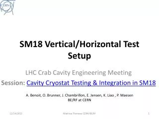
SF LHe G/LHe Thermal cycling on cryogenic test benches GHe @ 80K LHe @ 4.2K SF LHe @ 1.9K Cool-down • cool-down and warm-up greatly accelerated (2 weeks in LHC) • LHe bath at ambient pressure is made inside cold mass (40 kg LHe/dipole) • Heat exchanger carries innovative bi-phase superfluid He flow to subcool down to 1.9K warm-up with He @ 320K
Power tests • HV insulation tests: up to 3kV between coils, ground and quench heaters • Instrumentation tests: DAQ system and magnet instrumentation (voltage taps, T sensor) verified and calibrated • Quench protection system test: quench heaters are discharged in various combinations at the 1.5 kA level to verify time constants, max. induced voltages and currents, etc … • Training: field is repeatedly ramped up, and possibly quenched, until the ultimate field level is reached (9T).The location of the quench is systematically measured to assess quality of construction. • Special tests: e.g. provoked quenches at 4.2K to assess the current-carrying capability of the cable (short sample limit) • Provoked quench at 7T: empty He before warm-up Quenches are normally originated in the heads(complex 3D geometry + looser tolerances)Quenches originating in the straight part may point to fabrication defects
Training example: good dipole Ultimate field detraining Memory effect Nominal field
Training example: bad dipole Ultimate field No memory effect Nominal field
Magnetic measurements why magnetic measurements ? To qualify/accept magnets: - minimum level of performance must be guaranteed- harmonics measurement may spot construction errors For the machine: reliable operation requires detailed knowledge of: - transfer function to within 200 ppm- harmonics up to decapole to within 50 ppm- field direction to within ±1 mrad- dynamic effects modelling database • Loadline: local and integrated transfer function and harmonics as a function of steady-state excitation level • LHC cycle: quantify dynamic effects as they will occur in the real machine cycle (magnet is put in a reproducible clean state by means of a previous quench and current pre-cycle) • Coupling currents: systematic study of dynamic effects as a function of ramp rate and powering history • Field direction: average direction of the field w.r.t. cryostat fiducials • Magnetic axis: position of the axis (locus of B0) w.r.t. cryostat fiducials, used to define the precise position of the magnet in the tunnel and to assess the geometry in cold conditions.
Non-linear effects • Superconducting filament magnetization (persistent eddy currents) • large hysteresis with relative errors of the order of 10-3 at low field (injection) • hysteresis depends on temperature, current and current history • main field and multipoles affected in different ways • Linear regime (geometric contribution) • field is proportional to the current (can be computed with Biot-Savart’s law) • the T.F. depends only on the coil geometry injection • Iron saturation • affects only small area in the collar (B>2T) • relative errors of the order of 10-2 at high field • additional multipoles generated
Dynamic superconductor effects • Coupling currents effects • finite inter-filament and inter-strand resistance (RC) gives rise to loops linked with changing flux • multipole errors Ḃ, RC-1 • hysteresis depending in a complex way upon field level, temperature and powering history • Decay and snap-back • superconductor magnetization and coupling currents interact in a complex way to give long-term logarithmic time dependence effects (field decay) • hysteresis branch switching may occur at the end of a decay phase to cause sudden current redistribution and additional multipole errors (snap-back)
Magnetic measurement equipment: twin 15m harmonic coil shafts coil SiN flange+ bronze roller Micro-cableconnector shafts Ti bellows Twin Rotating Unit • 213 Al2O3 sectors carrying 3 rectangular coils each • cover the full length of the magnet to obtain integral in a single rotation (~ few seconds) • stiff torsionally, bending at joints to follow the curvature of the magnet • doubles up as an antenna for quench localization • resolution = 0.1 mT, 50 mrad; accuracy = 100 ppm
Magnetic measurement equipment: harmonic analysis “A” coil V(t) GV(t) F(q) G FFT A A-C Programmable amplifier “C” coil {An,Bn} Compensated (A-C) Absolute (A)
T travelling probe ( mole ) S Y X Laser tracker Alignment target (fiducial) LED light spot (optically projected in the centre of the coil) T XY measurement telescope CCD camera + DSP R Telescope Dipole S Magnet coordinate frame Magnetic axis LED light-spot(coil rotation axis) Reference support Telescope coordinate frame Magnetic axis measurement in dipoles Quadrupole Configured Dipole(“ugly quad”) Dipole axis measurement with a warm rotating coil mole + telescope tracker
Laser Tracker Survey Taylor-hobson 3.5’’ tooling ball Rotating head Retro-reflector • Laser tracker to detect 3D position of spherical optical targets (retro-reflector corner cubes) mounted on standard conical receptacles • Interferometer and phase modulation detector for distance measurement;2 16000 pt. incremental angular encoders for direction measurement • Nominal accuracy = 5 ppm = 50 mm @ 10 mReal-world repeatability = 150 mm @ 10 m • Measurement modes: static, cyclic, dynamic (< 1kHz) • Used for:- measurement of magnetic axis and field direction of dipoles and quadrupoles, warm and cold (moles, Chaconsa, 15m shafts benches)- geometric survey of auxiliary equipment (reference magnets) LEICA Tracker unit
References L Rossi, Superconducting magnets for the LHC main lattice, Presented at: 18th International Conference on Magnet Technology MT 18 , Iwate, Japan , 20 - 24 Oct 2003 M Allitt, R Wolf et al; Status of the Production of the LHC Superconducting Corrector Magnets Presented at: 18th International Conference on Magnet Technology MT 18 , Iwate, Japan , 20 - 24 Oct 2003 L Rossi, Superconducting Cable and Magnets for the Large Hadron Collider Presented at: 6th European Conference on Applied Superconductivity EUCAS 2003 , Sorrento, Napoli, Italy , 14 - 18 Sep 2003 W Scandale, E Todesco et al, Influence of Superconducting Cable Dimensions on Field Harmonics in the LHC Main Dipole, LHC Project Report 693 CERN Accelerator School on Superconductivity in Particle Accelerators, Hamburg 1995, CERN Yellow Report 96-03 The Large Hadron Collider – Conceptual Design, Report CERN/AC/95-05