Download
1 / 19
200 likes | 635 Views
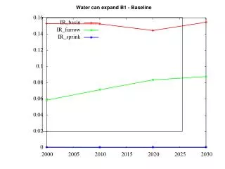
WATER CHILLER 취급 설명서. 고속 가공기 전용 냉각기. MODEL:DS–3000. 알 림. 본 제품 및 책자에서 설명하고 있는 내용은 사전통보 없이 변경될 수 있습니다 . 본 제품 및 책자에서 사용된 문장 및 사진 , 그림 , 도면의 저작권은 다원에 있으며 저작권자의 허락 없이 복사 및 복제 , 변경 , 재생산 , 인용 , 다른 언어로 번역할 경우 저작권법에 의해 처벌 받을 수 있습니다. 50 45 40 30 20 10 5. 실 온 (℃).

E N D
WATER CHILLER취급 설명서 고속 가공기 전용 냉각기 MODEL:DS–3000
알 림 본 제품 및 책자에서 설명하고 있는 내용은 사전통보 없이 변경될 수 있습니다. 본 제품 및 책자에서 사용된 문장 및 사진, 그림, 도면의 저작권은 다원에 있으며 저작권자의 허락 없이 복사 및 복제, 변경, 재생산, 인용, 다른 언어로 번역할 경우 저작권법에 의해 처벌 받을 수 있습니다
50 45 40 30 20 10 5 실 온 (℃) 5 10 20 30 40 50 입구 수온(℃) 주의 본체는 냉매로 R-22를 사용하고 있습니다. 지구 환경보호를 위해, 본체를 폐기 할 때는 필히 냉매를 회수하여 주십시오. Caution – R-22 is used as refrigerant with this equipment. Death or serious personal injury may result if personnel fail to observe proper safety precautions. To help protect environment, collect R-22 before disposal of the equipment 일반 주의 사항(General Precautions) (Operational Limitations) The following limitations are absolute and operation beyond these limits may cause serious damage to the equipment. Room temperature in Celsius Operational Limitations Water temperature at inlet in Celsius 2.사용유체 (Limitations on Liquid Usage)
설치시 주의사항(Installation and Operation Precautions ) • 설치장소(Installation Precautions) • 설치 장소는 다음과 같은 장소를 선택하여 주십시요. 1) 수평이고 단단한 장소.( 경사각 5° 이내) 2) 직사광선이나 열기를 직접 받지 않는 장소 3) 통풍이 잘되는 장소, 습기가 적은 장소 4) 배출된 공기가 다시 흡입되지 않는 장소 5) 배관 배선이 용이한 장소 6) 먼지,분지, 오일 비산이 등이 적은 장소 • 흡기, 배기구에서 500mm 사이에는 통풍에 장애가 되는 물건을 놓지 마십시요. • Site Preparation • * Secure the following when installing equipment • 1)Install unit on a flat foundation, level (within .5% difference from the horizontal), and firm • enough to withstand the weight of the unit. • 2)Do not set up the unit in the immediate vicinity of heat sources and do not expose to • direct sun light. • 3)Install the unit in well-ventilated areas, and avoid humidity. • 4)Avoid areas where exhaust air may be inhaled. • 5)Make sure the site has enough clearance to safely arrange water inlet/outlet lines • and pipes. • 6)Do not install the unit in areas where it may be exposed to excessive dust and arsenic • acid. • * Do not place any objects within 500mm of the inhaler/exhaust. (Water Pipe Arrangement) 2.수배관 1.급수 배관 연결 ->외부 규격에 맞게 연결하여 주십시요. - 수동 급수일 경우 수위 레벨게이지를 확인하여 항상 HIGH에 위치할수 있도록 보충하여 주십시요. 2. 배수 배관 연결 -> 장시간 사용하여 내부 오염물이 있을 경우 한번씩 잔여물을 빼내어 보충수를 교환하여 주십시요 -> 배수가 원할히 할 수 있도록 배관 및 밸브를 부착하여 주십시요. 3. 순환수 입출구 배관 -> 외부에 바이패스 배관을 하여 주십시요. -> 입출구 배관이 바뀌지 않도록 주의 하여 주십시요. ( 입구 배관은 외부 기계에서 냉각기 쪽으로 들어 오는 것입니다. 출구 배관은 냉각기에서 기계쪽으로 나가는 것입니다.)
운전시 주의사항 (Operation Precautions) 1.물이 없는 상태에서 운전은 절대 하지 마십시요.(순환펌프의 고장의 원인이 됩니다.) 2.수 배관내에 공기가 흡입되지 않도록 하여 주십시요. (공기 혼입은 소음의 원인이 됩니다.) 3. 냉각기 본체 외부의 배관 압력 손실이 큰 경우는 압력 손실을 최소화 하기 위하여 배관을 변경하여 주십시요. 사용 범위를 초과하여 사용하시면, 소음 및 고장의 원인이 되오니 주의하여 주십시요. 4.지연 타이머가 내장되어 있으므로, 압축기가 한번 정지후 또는 최초 가동시 동작하지 않을 경우가 있으나 고장이 아닙니다. • 1.Never operate this equipment without water. This results in damage to the water pump. • 2.Water channels shall be kept air-free. Influx of air causes excessive noise during operation. • 3.Rearrange pipes to eliminate excessive pressure drop in channels/pipes if you notice the • following: • a.Abnormally high water viscosity • b.Excessive pressure drop in external channels/pipes • *Operating this equipment beyond the operational limits specified results in increased noise • level and/or malfunctioning. • 4. Delay timer is installed in the unit. You may experience a delayed start of compressor at start-up or once it has been turned off. • ! Attention/Caution– Read and fully understand the Installation & Operation Instructions before operating this equipment. Know what you are doing.
모델별 계통도(DIAGRAM) 1.DS TYPE 형식 DS타입은 소형에서 대형 모두 가능하며 공냉식으로 산업 여러 분야에 적용되며 물탱크와 순환펌프가 내장되어 있습니다 DS -TYPE Specifications – Available in many sizes: from small-sized to oversized units. Air cooling modes. Comes with built-in oil tank and circulation pump.
제품구성 및 내용물(온도 조절기) Equipment Components and Functional Details (Temperature Controller) - 7 -
CONTROLLER DA-0812 10 WATER SENSOR 9 8 Transformer HIGH PRESSOR S/W 7 220v 6 FLOW S/W.PUMP OCR POWER input 24v 5 PUMP COMP 전기 결선 부분 (Electrical Connection/Wiring Precautions) • 전원부(Power Supply Part) POWER INPUT LINE은 전원공급을 위한 단자대입니다. N, L 단자에 AC220V 1¢를 공급합니다. COMP/FAN LINE은 N/L-C에 COMP가동시 전원 220V가 출력됩니다. PUMP LINE은 N/L-P에 PUMP가동시 전원 220V가 출력됩니다. The power input line is the terminal base designed to provide power supply to equipment. It supplies AC220V 1¢ to Terminals L and N. Install circuit breaker for your safety. ☞ 주의 3상 전원을 사용하는 냉각기의 경우 역상/결상을 감시하는 기능이 있으며 역상/결상 경보 시 POWER S/W ON 시켜도 표시창의 LED가 표시되지 않습니다. 이 경우 3상의 3선중 2가닥을 서로 바꾸어 역상경보를 해결하고 각 상간 전압을 측정하여 결상인 경우 전원공급경로를 확인하여 보수하시기 바랍니다. ! Attention/Caution The cooler’s 3-phase power supply comes with monitoring capacity for negative-phase or open phase sequence, and if phases are incorrectly wired, LED will not displayed on the control panel. To release disconnect 2 of the 3 wires of the 3-phase power supply, swap connect again and measure the voltage of each phase. If an open phase sequence is detected, check and repair the power supply channel ☞주의 총 부하의 합은 전류치 15A(저항부하)를 넘어서는 안 됩니다. ! Attention/Caution Total max load shall not be greater than 15A (resistance load) at any time. - 9 -
경보출력 Alarm Output com NO Flow Pump-ocR H-Press 8 7 5 6 Flow S/W Pump-ocR 안전차단 스위치 • 경보출력장치(Alarm Output Device) 경보의 출력은 C 접점으로 출력되며 최대 허용 부하는 AC250V 3A(저항부하) 이하로 한정합니다. BUZZ는 AC220C 3A(저항부하)로 출력되며 POWER를 OFF 시켜 정지합니다. Alarm output is sent through point of contact C. The normal load capacity limit is set to a maximum of AC250V 3A. Output is set at AC220C 3A (resistance load), and can be stopped pushing the “POWER S/W”OFF. • 안전차단 스위치 안전차단 스위치는 정상적인 상태에서 CLOSE되는 것을원칙으로 하며, OPEN되면 경보로 인식합니다. (The switches are set to remain CLOSED only in ordinary circumstances (when operation is normal). Otherwise, they OPEN up to generate alarm output and to signal warning/abnormal situations ) ☞ 주의 사용하지 않는 안전차단 스위치의 연결은꼭 +12V(+24V)단자와 연결해 두어야 합니다. (Safety circuit breaker switches which are not in use must remain connected to +12V(+24V) terminals. ) ☞ 주의 결선하지 않은 상태에서는 경보로 인식합니다. 경보의 스위치는 접점형식의 스위치를 사용하여주십시오. 반도체(무접점)스위치 등은 정상적 으로동작하지 않을 수 있습니다. Alarm switches not connected will be read as OPEN and warning situation. Use contact-types for alarm switches. Non-contact (semiconductors) switches may not properly function due to poor connectivity. - 10 -
▣. 안전차단 스위치에 의한 경보발생시 운전상태 (Operational Status Alarm Situation Initiated by Safety Circuit Breaker Switch ) • 온도 SENSOR (Temperature Sensor) 온도센서는 CN2 커넥터에 그림과 같이 연결하여 주십시오. 온도센서는 당사에서 지정한 센서만 사용하여주십시오. 지정되지 않은 센서는 온도가 틀리게 표 시 되거나 오동작이 발생될 수 있습니다 Connect temperature sensor to CN2 connector (see diagram). Use only genuine temperature sensors (or approved ones by Daeil). Unapproved sensors may deliver erroneous temperature values and/or result in malfunctioning. ▣. - 센서의 연장은 100M 까지 가능 하며 20M이상 연장 시 실드선을 사용하여주십시오. - 센서의 측정오차를 줄이기 위해 실드는 EARTH 결선하여 주십시오. - 센서의 결선 시 센서선의 극성에 구분 없이 결선합니다. Sensor can be extended up to 100m. When extending more than 20m, use shielding wires. Ground the shielding wires in order to minimize measurement error. Connect the sensor to sensor wires regardless of polarity of wires. - 11 -
운전 방법 1.단자대의 결선이 올바른지 확인하여 주십시오. 2.인가되는 입력전원이 정격전압인지 확인 후 전원을 인가하여 주십시오. 3.전기컨트롤 박스내의 전원스위치를 올려주십시오. 4.컨트롤러의 전원 버튼을 눌러 전원을 켜 주십시오. 5.설명서를 참조하여 설정온도 및 설치모드 설정값을 설정하여 주십시오. 6.순환 버튼을 눌러 순환펌프를 켜 주십시오. 7.순환펌프가 가동을 하는지 확인하여 주십시오. 8.순환이 원활한지 확인하여 주십시오. 9. 누수현상이 없는지 확인하여 주십시오. 10.펌프의 회전방향이 정 방향 인지 확인하여 주십시오. 11.냉각 버튼을 눌러 냉각기를 켜 주십시오. 12.냉각기가 정상운전 상태인지 확인하여 주십시오. *** 일반적으로 냉각기는 가동 전 약2~3분의 지연시간을 가지며 이것은 냉각기 냉매 사이클의 안정화를 위한 것입니다. 냉각기는 설정온도를 기준으로 자동으로 운전하며 설정온도를 유지 관리합니다. 13.경보 발생시 POWER S/W를 OFF 시킨 후 다시power S/W를 작동하면 정지됩니다. 14. 경보발생 시에는 본 장치의 상단에 부착된 사용설명 및 에러코드 표를 참조하여 처리 하시고 여의치 않을 경우 본사 A/S 담당부서로 문의 하여 주십시오. • 1.With master the power switch off, check to insure the power supply cable cross- • section and the electrical terminal clamps are tight and in order. • 2.Check the voltage of approved input power supply is the rated voltage. • 3.Connect (close) the circuit breaker located in the electricity control box. • 4.Turn on the unit. Press the power pushbutton on the controller. • 5.Set the desired/setting temperature and installation mode values. Refer to the • operating instructions. • 6.Turn on the circulation pump (Push Circulation). • 7.Check the circulation pump is operating properly. • 8.Check wateris circulating properly. • 9.Check forwater leakage. • 10.Check the pump is rotating in the positive/correct direction. • 11.Turn on Cooler (Press Cooling). • 12.Observe the cooler is operating properly. • a.Generally, the cooler takes approx. 2~3 minutes delay before operation begins. • This is to stabilize the cycle of refrigerant in the cooler. Cooler adjusts its operation • automatically to reach/realize and maintain the temperature setting • 13. If the alarm sounds, push ‘alarm reset’ pushbutton to stop it. • 14.If a power outage occurrs or a circuit breaker opens, cut power supply during • operation, the unit will resume operation at its previously set mode and conditions. - 12 -
주요 기능 (Important Functions) • 기능의 전계( Functions) - 13 -
온도 설정 방법(Setting Temperature) - power 스위치를 ON 시켜 전원을 인가 시킵니다. - SET 버튼을 2초 누르고 있으면 설정모드로 진입 합니다.. - 현재온도 표시 창에 가 표시하고, SET 버튼을 다시 한번 누르면 표시 창에는 설정되어 있던 설정값이 표시 됩니다. - UP / DN 버튼을 이용하여 유지할 온도를 설정 합니다. - 3초 동안 아무 버튼도 조작하지 않으면 설정값이 저장되어 현재 온도 표시창으로 전환됩니다. 1. Power switch “on” 2.Click or push SET pushbutton only once. 3.‘Set’ will appear on LED “” and previously set temperature value will flash on LED “Setting Temp.” 4.Using Up/Dn pushbuttons, set desired temperature value. 5.To save, push SET pushbutton once again. SAV (Save) will appear while the system stores this information. 6.When no action is taken for more than 3 seconds prior to step 4, the system will resume normal mode without saving 기타 모드 설정 방법(Setting Installation Modes) ①. 설치 모드로 진입하려면 SET 버튼을 2초간 계속 누르고 있습니다. ②. 설정온도 표시 창에 SET가 표시되다 문자가 점멸 표시되면손을 뗍니다. ③. 설정 모드의 이동방법은 SET 버튼을 짧게 한번씩 누를 때마다 ⇒ ⇒ 23.0 ⇒ ⇒ ⇒ ⇒ ⇒ ⇒ 120 0.0 ⇒ 0.5 40 ⇒ 순으로 이동하게 됩니다. 10 ⇒ - 3초 동안 아무 버튼도 조작하지 않으면 저장하고 현재온도 표시가 됩니다. ④. 수정할 설정모드에서 UP 버튼나 DN 버튼을 눌러 설정치를 수정합니다. ⑤. 수정한 설정값을 저장하려면 SET 버튼에 손을 떼면 3초후에 저장 되여 현재온도가 표시 됩니다. 1.Push the SET pushbutton for about 2 seconds. 2.When ‘Set’ is displayed on the LED “Current Temp.” disappears and appears flashing, release your finger from the SET pushbutton. 3.Press SET pushbutton briefly to change the menu setting. Every time you press SET pushbutton, the following menu settings will appear on LED: 4.When the desired setting modes flashes on LED, press Up/Dn pushbuttons to modify values. 5.To save values, push SET pushbuttons again for about 3 seconds. SAV will appear while the system updates, and operation will return to the normal mode. ⇒ 23.0 ⇒ ⇒ 120 ⇒ ⇒ ⇒ ⇒ ⇒ ⇒ 0.0 ⇒ 0.5 ⇒ 10 40 - 14 -
절대제어 운전(Constant Control Operation) 1.절대제어 운전( Constant Control Operation) - 절대제어 운전이란 일반적인 운전방식으로 설정온도 표시 창에 표시된 설정온도를 기준으로 운전하는 방식입니다. - 예) 설정온도를 25.0℃로 설정하였을 때 25.0℃를 기준으로 ON/OFF제어됩니다. -At constant control operation mode, the system operates on the basis of a temperature setting displayed on the LED ‘setting/room temp.’ -For example, if the temperature value is set at 25.0C, the operation of cooler will be stop and resume around 25.0C. → 지연시간( ) : 냉각기는 정지한 후 일정시간의 휴식을 요하는데 이는 냉매의 불안정으로 인하여 발생할 수 있는 컴프레서의 과부하 손상을 방지하기 위하여 필요한 최소한의 정지시간으로 주어집니다. 지연시간 진행 중 작동온도 조건이 될 경우 지연되는 동안 냉각 램프는 점멸 표시됩니다. 지연시간이 지난 후에는 지연시간을 가지지 않습니다. -Delay time (dLT): Cooler requires a certain non-operative period once it comes to a full stop. This is to stabilize the cycle of refrigerant in the cooler and to prevent the refrigerant while in an unstable state from potentially damaging the compressor by imposing an overload. If the operative temperature and conditions are met before the end of delay period, only the cooling lamp/LED will flash for the remaining delay time. Once the given/preset delay period expires, the cooler can resume or start operation immediately. - 14 -
경 보 코 드 Alarm and error code is displayed on LED - 16 -