Download
1 / 29
320 likes | 615 Views
PIPELINING AND VECTOR PROCESSING. Parallel Processing Pipelining Arithmetic Pipeline Instruction Pipeline RISC Pipeline Vector Processing Array Processors(refer book). Parallel Processing. PARALLEL PROCESSING. Execution of Concurrent Events in the computing

E N D
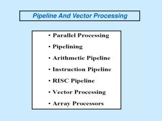
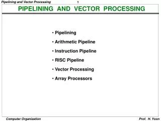
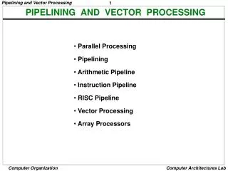
PIPELINING AND VECTOR PROCESSING • Parallel Processing • Pipelining • Arithmetic Pipeline • Instruction Pipeline • RISC Pipeline • Vector Processing • Array Processors(refer book)
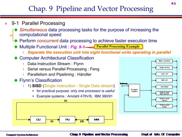
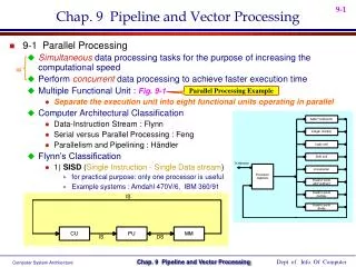
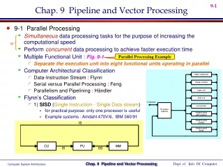
Parallel Processing PARALLEL PROCESSING • Execution of Concurrent Events in the computing • process to achieve faster Computational Speed Levels of Parallel Processing - Job or Program level - Task or Procedure level - Inter-Instruction level - Intra-Instruction level
Flynn's classification Based on the multiplicity of Instruction Streams and Data Streams Instruction Stream Sequence of Instructions read from memory Data Stream Operations performed on the data in the processor Parallel Processing PARALLEL COMPUTERS Architectural Classification Number of Data Streams Single Multiple Number of Instruction Streams Single SIMD SISD Multiple MISD MIMD
Parallel Processing COMPUTER ARCHITECTURES FOR PARALLEL PROCESSING Superscalar processors Superpipelined processors VLIW Nonexistence Array processors Systolic arrays Associative processors Shared-memory multiprocessors Bus based Crossbar switch based Multistage IN based Message-passing multicomputers Hypercube Mesh Reconfigurable SISD MISD SIMD MIMD Von-Neuman based Dataflow Reduction
Parallel Processing SISD COMPUTER SYSTEMS Memory Control Unit Processor Unit Data stream Instruction stream Characteristics - Standard von Neumann machine - Instructions and data are stored in memory - One operation at a time Limitations Von Neumann bottleneck Maximum speed of the system is limited by the Memory Bandwidth (bits/sec or bytes/sec) - Limitation on Memory Bandwidth - Memory is shared by CPU and I/O
Parallel Processing MISD COMPUTER SYSTEMS M CU P M CU P Memory • • • • • • Data stream M CU P Instruction stream Characteristics - There is no computer at present that can be classified as MISD
Parallel Processing SIMD COMPUTER SYSTEMS Memory Data bus Control Unit Instruction stream P P P Processor units • • • Data stream Alignment network Memory modules M M M • • • Characteristics - Only one copy of the program exists - A single controller executes one instruction at a time
Parallel Processing MIMD COMPUTER SYSTEMS M M M P P P • • • Interconnection Network Shared Memory Characteristics - Multiple processing units - Execution of multiple instructions on multiple data Types of MIMD computer systems - Shared memory multiprocessors - Message-passing multicomputers
Pipelining PIPELINING • A technique of decomposing a sequential process • into suboperations, with each subprocess being • executed in a partial dedicated segment that • operates concurrently with all other segments. Ai * Bi + Ci for i = 1, 2, 3, ... , 7 Memory Ai Bi Ci Segment 1 R1 R2 Multiplier Segment 2 R4 R3 Adder Segment 3 R5 R1 Ai, R2 Bi Load Ai and Bi R3 R1 * R2, R4 Ci Multiply and load Ci R5 R3 + R4 Add
Pipelining OPERATIONS IN EACH PIPELINE STAGE Clock Pulse Segment 2 Segment 3 Segment 1 • Number R1 R2 R3 R4 R5 • 1 A1 B1 • 2 A2 B2 A1 * B1 C1 • 3 A3 B3 A2 * B2 C2 A1 * B1 + C1 • 4 A4 B4 A3 * B3 C3 A2 * B2 + C2 • 5 A5 B5 A4 * B4 C4 A3 * B3 + C3 • 6 A6 B6 A5 * B5 C5 A4 * B4 + C4 • 7 A7 B7 A6 * B6 C6 A5 * B5 + C5 • 8 A7 * B7 C7 A6 * B6 + C6 • 9 A7 * B7 + C7
Pipelining GENERAL PIPELINE General Structure of a 4-Segment Pipeline Clock Input S R S R S R S R 1 1 2 2 3 3 4 4 Space-Time Diagram 1 2 3 4 5 6 7 8 9 Clock cycles Segment T4 1 T1 T2 T3 T5 T6 2 T4 T6 T1 T2 T3 T5 3 T1 T2 T3 T4 T5 T6 T1 T2 T3 T4 T5 T6 4
Pipelining tn lim ( = k, if tn = k * tp ) Sk = tp n PIPELINE SPEEDUP • n: Number of tasks to be performed • Conventional Machine (Non-Pipelined) • tn: Clock cycle • t1: Time required to complete the n tasks • t1 = n * tn • Pipelined Machine (k stages) • tp: Clock cycle (time to complete each suboperation) • tk: Time required to complete the n tasks • tk = (k + n - 1) * tp • Speedup • Sk: Speedup • Sk = n*tn / (k + n - 1)*tp
Pipelining PIPELINE AND MULTIPLE FUNCTION UNITS Example - 4-stage pipeline - subopertion in each stage; tp = 20nS - 100 tasks to be executed - 1 task in non-pipelined system; 20*4 = 80nS Pipelined System (k + n - 1)*tp = (4 + 99) * 20 = 2060nS Non-Pipelined System n*k*tp = 100 * 80 = 8000nS Speedup Sk = 8000 / 2060 = 3.88 4-Stage Pipeline is basically identical to the system with 4 identical function units Multiple Functional Units
Arithmetic Pipeline Exponents Mantissas a b A B R R Compare Difference Segment 1: exponents by subtraction R Align mantissa Choose exponent Segment 2: R Add or subtract Segment 3: mantissas R R Adjust Normalize Segment 4: exponent result R R ARITHMETIC PIPELINE Floating-point adder X = A x 2a Y = B x 2b [1] Compare the exponents [2] Align the mantissa [3] Add/sub the mantissa [4] Normalize the result
Instruction Pipeline INSTRUCTION CYCLE Six Phases* in an Instruction Cycle [1] Fetch an instruction from memory [2] Decode the instruction [3] Calculate the effective address of the operand [4] Fetch the operands from memory [5] Execute the operation [6] Store the result in the proper place * Some instructions skip some phases * Effective address calculation can be done in the part of the decoding phase * Storage of the operation result into a register is done automatically in the execution phase ==> 4-Stage Pipeline [1] FI: Fetch an instruction from memory [2] DA: Decode the instruction and calculate the effective address of the operand [3] FO: Fetch the operand [4] EX: Execute the operation
Instruction Pipeline INSTRUCTION PIPELINE Execution of Three Instructions in a 4-Stage Pipeline Conventional i FI DA FO EX i+1 FI DA FO EX i+2 FI DA FO EX Pipelined i DA FI FO EX i+1 FI DA FO EX i+2 DA EX FI FO
Instruction Pipeline Step: 1 2 3 4 5 6 7 8 9 10 11 12 13 Instruction 1 FI DA FO EX 2 FI DA FO EX FI DA FO EX 3 (Branch) 4 FI FI DA FO EX FI DA FO EX 5 FI DA FO EX 6 7 FI DA FO EX INSTRUCTION EXECUTION IN A 4-STAGE PIPELINE Fetch instruction Segment1: from memory Decode instruction and calculate Segment2: effective address Branch? yes no Fetch operand Segment3: from memory Execute instruction Segment4: yes Interrupt Interrupt? handling no Update PC Empty pipe
Instruction Pipeline MAJOR HAZARDS IN PIPELINED EXECUTION • Structural hazards(Resource Conflicts) • caused by access to memory by two segments at the same time. • Most of these conflicts can be resolved by using separate instruction • and data memories. • Data hazards (Data Dependency Conflicts) • An instruction scheduled to be executed in the pipeline requires the • result of a previous instruction, which is not yet available Data dependency ADD DA B,C + • R1 <- B + C • R1 <- R1 + 1 INC DA bubble R1 +1 • Control hazards • Branches and other instructions that change the PC • make the fetch of the next instruction to be delayed JMP ID PC + PC Branch address dependency OE OS bubble IF ID OF Hazards in pipelines may make it necessary to stallthe pipeline Pipeline Interlock: Detect Hazards Stall until it is cleared
Instruction Pipeline STRUCTURAL HAZARDS Structural Hazards(Resource conflicts) Occur when some resource has not been duplicated enough to allow all combinations of instructions in the pipeline to execute Example: With one memory, a data and an instruction fetch cannot be initiated in the same clock i FI DA FO EX i+1 FI DA FO EX i+2 FI DA FO EX stall stall The Pipeline is stalled for resource conflict <- Two Loads with one port memory -> Two-port memory will serve without stall
Instruction Pipeline DATA HAZARDS Data Hazards Occurs when the execution of an instruction depends on the results of a previous instruction ADD R1, R2, R3 SUB R4, R1, R5 Data hazard can be dealt with either hardware techniques or software technique Hardware Technique Interlock - hardware detects the data dependencies and delays the scheduling of the dependent instruction by stalling enough clock cycles Forwarding (bypassing, short-circuiting) - Accomplished by a data path that routes a value from a source (usually an ALU) to a user, bypassing a designated register. This allows the value to be produced to be used at an earlier stage in the pipeline than would otherwise be possible Software Technique The compiler is designed to detect a data conflict and reorder instructions As necessary to delay the loading of the conflicting data by inserting no-operation instructions.This method is called DELAY LOAD
Instruction Pipeline CONTROL HAZARDS(Branching Difficulties) Branch Instructions - Branch target address is not known until the branch instruction is decoded. - Stall -> waste of cycle times Branch Instruction FI DA FO EX Next Instruction FI DA FO EX Target address available Dealing with Control Hazards * Prefetch Target Instruction * Branch Target Buffer * Loop Buffer * Branch Prediction * Delayed Branch
Prefetch Target Instruction Fetch instructions in both streams, instruction to be executed if branch not taken and the instruction if branch taken Both are saved until branch branch is executed. Then, select the right instruction stream and discard the wrong stream Branch Target Buffer(BTB; Associative Memory) Present in the fetch segment of the pipeline. It has entry of the Address of previously executed branches i.e. their Target instruction and the next few instructions When fetching an instruction, search BTB. If found, fetch the instruction stream in BTB; If not, new stream is fetched and update BTB Loop Buffer(High Speed Register file) A variation of BTB. A register file maintained by the instruction fetch segment of the pipeline. Register file stores the entire loop that allows to execute a loop without accessing memory Branch Prediction Uses additional logic to guess the outcome of the branch condition before it is executed. The instruction is fetched based on the guess. Correct guess eliminates the branch penalty Delayed Branch Compiler detects the branch and rearranges the instruction sequence by inserting useful instructions that keep the pipeline busy in the presence of a branch instruction Instruction Pipeline CONTROL HAZARDS
RISC Pipeline RISC PIPELINE RISC - Machine with a very fast clock cycle that executes at the rate of one instruction per cycle <- Simple Instruction Set Fixed Length Instruction Format Register-to-Register Operations Instruction Cycles of Three-Stage Instruction Pipeline Data Manipulation Instructions I: Instruction Fetch A: Decode, Read Registers, ALU Operations E: Write a Register Load and Store Instructions I: Instruction Fetch A: Decode, Evaluate Effective Address E: Register-to-Memory or Memory-to-Register Program Control Instructions I: Instruction Fetch A: Decode, Evaluate Branch Address E: Write Register(PC)
RISC Pipeline DELAYED LOAD IN RISC PIPELINE • LOAD: R1 M[address 1] • LOAD: R2 M[address 2] • ADD: R3 R1 + R2 • STORE: M[address 3] R3 Three-segment pipeline timing Pipeline timing with data conflict clock cycle 1 2 3 4 5 6 Load R1 I A E Load R2 I A E Add R1+R2 I A E Store R3 I A E Pipeline timing with delayed load clock cycle 1 2 3 4 5 6 7 Load R1 I A E Load R2 I A E NOP I A E Add R1+R2 I A E Store R3 I A E The data dependency is taken care by the compiler rather than the hardware
RISC Pipeline DELAYED BRANCH Compiler analyzes the instructions before and after the branch and rearranges the program sequence by inserting useful instructions in the delay steps Using no-operation instructions Rearranging the instructions
Vector Processing Applications Problems that can be efficiently formulated in terms of vectors Long-range weather forecasting Petroleum explorations Seismic data analysis Medical diagnosis Aerodynamics and space flight simulations Artificial intelligence and expert systems Mapping the human genome Image processing Vector Processor (computer) Ability to process vectors, and related data structures such as matrices and multi-dimensional arrays, much faster than conventional computers Vector Processors may also be pipelined Vector Processing VECTOR PROCESSING
Vector Processing VECTOR PROGRAMMING DO 20 I = 1, 100 20 C(I) = B(I) + A(I) Conventional computer Initialize I = 0 20 Read A(I) Read B(I) Store C(I) = A(I) + B(I) Increment I = i + 1 If I 100 goto 20 Vector computer C(1:100) = A(1:100) + B(1:100)
Vector Processing VECTOR INSTRUCTION FORMAT Vector Instruction Format Pipeline for Inner Product of Matrix Multiplication C= A1 B1 + A5B5 + A9 B9 + A13 B13 +…….+ Ak Bk K may be equal to 100 or even 1000 The values of A and B are either in memory or in processor registers. Each floating point adder and multiplier unit is supposed to have 4 segments. All segment registers are initially initialized to zero. Therefore the output of the adder is zero for the first 8 cycles until both the pipes are full. Ai and Bi are brought in and multiplied at a rate of one pair per cycle. After 4 cycles the products are added to the Output of the adder. During the next 4 cycles zero is added. At the end of the 8th cycle the first four products A1B1 through A4B4 are in the four adder segments and the next four products A5 B5 through A8B8 are in the multiplier Segments. Thus the 9th cycle and onwards starts breaking down the summation into four sections:
C= A1 B1 + A5B5 + A9 B9 + A13 B13 +……. + A2 B2 + A6 B6 + A10 B10 + A14 B14 +……. + A3 B3 + A7 B7 + A11 B11 + A15 B15 +….. + A4 B4 + A8 B8 + A12 B12 + A16 B16 +…. For Array processors and memory interleaving refer Morris Mano page number chapter 9 page no:324 and 326