Download
1 / 36
360 likes | 368 Views
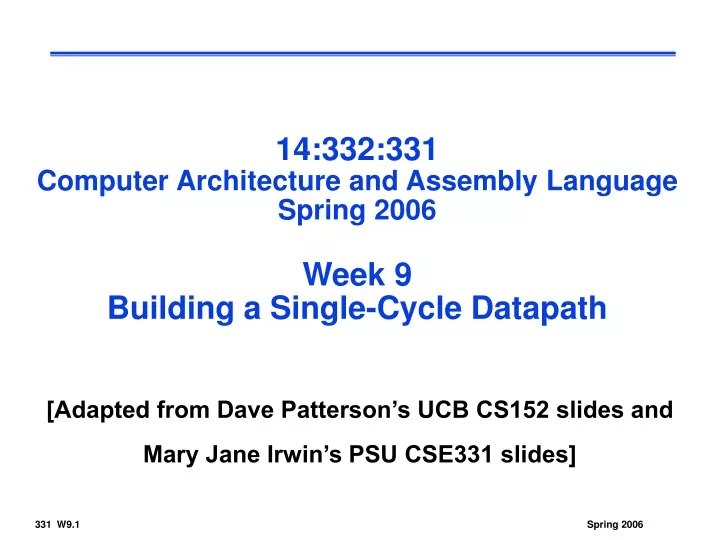
14:332:331 Computer Architecture and Assembly Language Spring 2006 Week 9 Building a Single-Cycle Datapath. [Adapted from Dave Patterson’s UCB CS152 slides and Mary Jane Irwin’s PSU CSE331 slides]. Head’s Up. This week’s material Building a MIPS single-cycle datapath

E N D
14:332:331Computer Architecture and Assembly LanguageSpring 2006Week 9Building a Single-Cycle Datapath [Adapted from Dave Patterson’s UCB CS152 slides and Mary Jane Irwin’s PSU CSE331 slides]
Head’s Up • This week’s material • Building a MIPS single-cycle datapath • Reading assignment – PH 5.4
Review: Abstract Implementation View • Split memory (Harvard) model - single cycle operation • Simplified to contain only the instructions: • memory-reference instructions: lw, sw • arithmetic-logical instructions: add, sub, and, or, slt • control flow instructions: beq, j • Sequential components (PC, RegFile, Memory) are edge triggered • state elements are written on every clock cycle; if not, need explicit write control signal • write occurs only when both the write control is asserted and the clock edge occurs Write Data Instruction Memory Address Read Data Register File Reg Addr Data Memory Read Data PC Address Instruction ALU Reg Addr Read Data Write Data Reg Addr
Example • Let’s modify the ISA and remove the ability to specify an offset for memory access instructions. Specifically, the load-store instructions would contain only two registers. In other words, all MIPS load-store instructions with offsets would become pseudoinstructions and would be implemented using two instructions: lw $t0, 104($t1) =>
RegWrite ALU control MemWrite overflow zero Read Addr 1 Read Data 1 Address Register File Read Addr 2 Instruction Data Memory Read Data ALU Write Addr Read Data 2 Write Data Write Data MemRead Sign Extend Example cont’d 18 17 17 16-bit offset 16 32
Creating a Single Datapath from the Parts • Assemble the datapath segments from the last lecture, add control lines as needed, and design the control path • Fetch, decode and execute each instructions in one clock cycle – single cycle design • no datapath resource can be used more than once per instruction, so some must be duplicated (e.g., why we have a separate Instruction Memory and Data Memory) • to share datapath elements between two different instruction classes will need multiplexors at the input of the shared elements with control lines to do the selection • Cycle time is determined by length of the longest path
Add RegWrite ALU control MemWrite 4 ovf zero Read Addr 1 Instruction Memory Read Data 1 Address Register File Read Addr 2 Data Memory Read Address PC Instruction Read Data ALU Write Addr Read Data 2 Write Data Write Data MemRead Sign Extend 16 32 Fetch, R, and Memory Access Portions R lw lw / sw R
Add RegWrite ALUSrc ALU control MemWrite MemtoReg 4 ovf zero Read Addr 1 Instruction Memory Read Data 1 Address Register File Read Addr 2 Data Memory Read Address PC Instruction Read Data ALU Write Addr Read Data 2 Write Data Write Data MemRead Sign Extend 16 32 Multiplexor Insertion
Branch not taken, R, lw /sw Add Add 4 Shift left 2 PCSrc RegWrite ALUSrc ALU control MemWrite MemtoReg ovf zero Read Addr 1 Instruction Memory Read Data 1 Address Register File Read Addr 2 Data Memory lw Read Address PC Instruction Read Data R ALU Write Addr Read Data 2 Write Data Write Data R lw / sw MemRead Sign Extend 16 32 Adding the Branch Portion
31 25 20 15 10 5 0 R-type: op rs rt rd shamt funct 31 25 20 15 0 I-Type: address offset op rs rt Adding the Control • Selecting the operations to perform (ALU, Register File and Memory read/write) • Controlling the flow of data (multiplexor inputs) • Information comes from the 32 bits of the instruction • Observations • op field always in bits 31-26 • addr of two registers to be read are always specified by the rs and rt fields (bits 25-21 and 20-16) • addr. of register to be written is in one of two places – in rt (bits 20-16) for lw; in rd (bits 15-11) for R-type instructions • base register for lw and sw always in rs (bits 25-21) • offset for beq, lw, and sw always in bits 15-0
0 1 PCSrc RegDst RegWrite ALUSrc MemWrite MemtoReg 0 1 0 1 0 1 MemRead ALU control Instr[5-0] ALUOp (Almost) Complete Single Cycle Datapath Add Add 4 Shift left 2 ovf Instr[25-21] Read Addr 1 Instruction Memory Read Data 1 Address Register File Instr[20-16] zero Read Addr 2 Data Memory Read Address PC Instr[31-0] Read Data ALU Write Addr Read Data 2 Write Data Instr[15 -11] Write Data Instr[15-0] Sign Extend 16 32
ALU Control • ALU's operation based on instruction type and function code
ALU Control, Con’t • Controlling the ALU makes use of multiple levels of decoding • main control unit generates the ALUOp bits • ALU control unit generates ALU control inputs
ALU Control Truth Table • Can make use of more don’t cares • since ALUOp does not use the encoding 11 • since F5 and F4 are always 10 • Logic comes from the K-maps …
(Almost) Complete Datapath with Control Unit 0 Add Add 1 4 Shift left 2 PCSrc ALUOp Branch MemRead Instr[31-26] Control Unit MemtoReg MemWrite ALUSrc RegWrite RegDst ovf Instr[25-21] Read Addr 1 Instruction Memory Read Data 1 Address Register File Instr[20-16] zero Read Addr 2 Data Memory Read Address PC Instr[31-0] 0 Read Data 1 ALU Write Addr Read Data 2 0 1 Write Data 0 Instr[15 -11] Write Data 1 Instr[15-0] Sign Extend ALU control 16 32 Instr[5-0]
R-type Instruction Data/Control Flow 0 Add Add 1 4 Shift left 2 PCSrc ALUOp Branch MemRead Instr[31-26] Control Unit MemtoReg MemWrite ALUSrc RegWrite RegDst ovf Instr[25-21] Read Addr 1 Instruction Memory Read Data 1 Address Register File Instr[20-16] zero Read Addr 2 Data Memory Read Address PC Instr[31-0] 0 Read Data 1 ALU Write Addr Read Data 2 0 1 Write Data 0 Instr[15 -11] Write Data 1 Instr[15-0] Sign Extend ALU control 16 32 Instr[5-0]
Store Word Instruction Data/Control Flow 0 Add Add 1 4 Shift left 2 PCSrc ALUOp Branch MemRead Instr[31-26] Control Unit MemtoReg MemWrite ALUSrc RegWrite RegDst ovf Instr[25-21] Read Addr 1 Instruction Memory Read Data 1 Address Register File Instr[20-16] zero Read Addr 2 Data Memory Read Address PC Instr[31-0] 0 Read Data 1 ALU Write Addr Read Data 2 0 1 Write Data 0 Instr[15 -11] Write Data 1 Instr[15-0] Sign Extend ALU control 16 32 Instr[5-0]
Load Word Instruction Data/Control Flow 0 Add Add 1 4 Shift left 2 PCSrc ALUOp Branch MemRead Instr[31-26] Control Unit MemtoReg MemWrite ALUSrc RegWrite RegDst ovf Instr[25-21] Read Addr 1 Instruction Memory Read Data 1 Address Instr[20-16] Register File zero Read Addr 2 Data Memory Read Address PC Instr[31-0] 0 Read Data 1 ALU Write Addr Read Data 2 0 1 Write Data 0 Instr[15 -11] Write Data 1 Instr[15-0] Sign Extend ALU control 16 32 Instr[5-0]
Branch Instruction Data/Control Flow 0 Add Add 1 4 Shift left 2 PCSrc ALUOp Branch MemRead Instr[31-26] Control Unit MemtoReg MemWrite ALUSrc RegWrite RegDst ovf Instr[25-21] Read Addr 1 Instruction Memory Read Data 1 Address Instr[20-16] Register File zero Read Addr 2 Data Memory Read Address PC Instr[31-0] 0 Read Data 1 ALU Write Addr Read Data 2 0 1 Write Data 0 Instr[15 -11] Write Data 1 Instr[15-0] Sign Extend ALU control 16 32 Instr[5-0]
Control Unit Logic • From the truth table can design the Main Control logic Instr[31] Instr[30] Instr[29] Instr[28] Instr[27] Instr[26] R-type lw sw beq RegDst ALUSrc MemtoReg RegWrite MemRead MemWrite Branch ALUOp1 ALUOp0
Adding the Jump Operation Instr[25-0] 1 Shift left 2 28 32 26 0 PC+4[31-28] 0 Add Add 1 4 Shift left 2 PCSrc Jump ALUOp Branch MemRead Instr[31-26] Control Unit MemtoReg MemWrite ALUSrc RegWrite RegDst ovf Instr[25-21] Read Addr 1 Instruction Memory Read Data 1 Address Register File Instr[20-16] zero Read Addr 2 Data Memory Read Address PC Instr[31-0] 0 Read Data 1 ALU Write Addr Read Data 2 0 1 Write Data 0 Instr[15 -11] Write Data 1 Instr[15-0] Sign Extend ALU control 16 32 Instr[5-0]
Single Cycle Implementation Cycle Time • Unfortunately, though simple, the single cycle approach is not used because it is inefficient • Clock cycle must have the same length for every instruction • What is the longest path (slowest instruction)?
Instruction Critical Paths • Calculate cycle time assuming negligible delays (for muxes, control unit, sign extend, PC access, shift left 2, wires) except: • Instruction and Data Memory (2ns) • ALU and adders (2ns) • Register File access (reads or writes) (1ns)
IR Address Memory A Read Addr 1 PC Read Data 1 Register File Read Addr 2 Read Data (Instr. or Data) ALUout ALU Write Addr Write Data Read Data 2 B Write Data MDR Where We are Headed • Problems with single cycle datapath design • uses clock cycle inefficiently • and what if we had a more complicated instruction like floating point multiply? • wasteful of area • Another approach • use a “smaller” cycle time • have different instructions take different numbers of cycles • a “multicycle” datapath:
Complete Datapath Instr[25-0] 1 Shift left 2 28 32 26 0 PC+4[31-28] 0 Add Add 1 4 Shift left 2 PCSrc Jump ALUOp Branch MemRead Instr[31-26] Control Unit MemtoReg MemWrite ALUSrc RegWrite RegDst ovf Instr[25-21] Read Addr 1 Instruction Memory Read Data 1 Address Register File Instr[20-16] zero Read Addr 2 Data Memory Read Address PC Instr[31-0] 0 Read Data 1 ALU Write Addr Read Data 2 0 1 Write Data 0 Instr[15 -11] Write Data 1 Instr[15-0] Sign Extend ALU control 16 32 Instr[5-0]
Example II: cycle length • Calculate cycle time assuming negligible delays (for muxes, control unit, sign extend, PC access, shift left 2, wires) except: • Instruction and Data Memory (2ns) • ALU (2ns) • Register File access (reads or writes) (1ns) • Adder for PC+4 (5ns) • Adder for branch address computation (5ns)
Example III: • Describe the effect that a single stuck-at-0 fault (I.e., regardless of what it should be, the signal is always 0) would have on the multiplexors in the single-cycle datapath. Which instruction, if any, would still work? Consider each of the following faults separately: RegDst = 0, ALUSrc = 0, MemtoReg = 0, Zero = 0;
Example IV: • We wish to add the instruction addi to the single-cycle datapath. Add any necessary datapaths and control signals.
Complete Datapath Instr[25-0] 1 Shift left 2 28 32 26 0 PC+4[31-28] 0 Add Add 1 4 Shift left 2 PCSrc Jump ALUOp Branch MemRead Instr[31-26] Control Unit MemtoReg MemWrite ALUSrc RegWrite RegDst ovf Instr[25-21] Read Addr 1 Instruction Memory Read Data 1 Address Register File Instr[20-16] zero Read Addr 2 Data Memory Read Address PC Instr[31-0] 0 Read Data 1 ALU Write Addr Read Data 2 0 1 Write Data 0 Instr[15 -11] Write Data 1 Instr[15-0] Sign Extend ALU control 16 32 Instr[5-0]
Example V: add jal Instr[25-0] 1 Shift left 2 28 32 26 0 PC+4[31-28] 0 Add Add 1 4 Shift left 2 PCSrc Jump ALUOp Branch MemRead Instr[31-26] Control Unit MemtoReg MemWrite ALUSrc RegDst1 RegWrite RegDst ovf Instr[25-21] MemtoReg1 Read Addr 1 Instruction Memory Read Data 1 Address Register File Instr[20-16] zero Read Addr 2 Instr[31-0] Data Memory Read Address 1 PC 0 ALU Write Addr 31 Read Data 2 0 Read Data 1 1 0 Write Data Write Data 1 Instr[15 -11] 0 Instr[15-0] Sign Extend ALU control 16 32 Instr[5-0]