Download
1 / 38
380 likes | 453 Views
Conceptual Model: Rapid Cyclogenesis. How to use MSG satellite images similarities to and improvements over MTP. Contact person: Veronika Zwatz-Meise zwatz-meise@zamg.ac.at Version 1.0. 13 July 2004. CM: Rapid cyclogenesis. MTP channels in comparison with the corresponding MSG channels

E N D
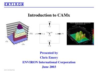
Conceptual Model: Rapid Cyclogenesis How to use MSG satellite images similarities to and improvements over MTP Contact person: Veronika Zwatz-Meise zwatz-meise@zamg.ac.at Version 1.0. 13 July 2004
CM:Rapid cyclogenesis • MTP channels in comparison with the corresponding MSG channels • CM Rapid cyclogenesis: IR image + relevant NWP parameters • MSG additional channels + Channel combinations • (WV and WV difference images)
IR sequence • Multilevel frontal cloud band • Low cloud head at rear side of frontal cloud band • Rapid dissolution of cloud at the rear side of the low cloud head • Rapid development of spiral structure • Development of Cbs at developed cloud spiral
MTP: IR/03 UTC As the image time between MTP and MSG differs, a shift between the cloud systems can be noticed in the two images
Sharper contours through improved space resolution; consecutive sequence only from MSG MSG: CH09/03 UTC
WV sequence • Dark stripe in WV approaches the cloud head area • Dark stripe becomes darker and begins to dissolve cloud at the rear edge of the cloud head area • In Ch05 double structure of the dark stripe with different developments visible • Refinement of CM possible ?! • Development of a dark area in the spiral center
Sharper contours through improved space resolution; consecutive sequence only from MSG; In MSG two WV channels: Ch05: WV information from high layers MSG: CH05/03 UTC
In MSG two WV channels Ch06: gives more information from lower layers when comapres Ch05; double structure of black stripes only in last time period resognisable - downward protrusion of dry air MSG: CH06/03 UTC
CM:Rapid Cyclogenesis • MTP Satellite images • MTP channels in comparison with the corresponding MSG channels • CM Rapid cyclogenesis: IR/WV image + relevant NWP parameters • MSG additional channels + Channel combinations • (WV and WV difference images)
Ch09; equ.thickness TFP Frontal characteristics in high gradient of thickness and TFP; high thickness gradient in cloud head area
Ch09; TA 700 hpa Frontal characteristics well seen in TA at 700 hPa: WA shield and CA behind CF
Ch09; Height contours 1000 hPa Distinct pressure minimum close to the surface (1000 hPa)
Ch09; height contours 500 hPa Upper level trough at the rear side of the cloud head
Ch09; jet streak 300 hPa Distinct jet streak from N, NW; bending to western orientation; cloud head in exit region
Ch09; jet streak PVA 300 hPa Distinct PVA max at 300 hPa in left exit region of the jet streak and in the cloud head area; PVA max close to the jet axis: shear and curvature vorticity
Ch09; height of PV = 2 units Stratospheric air (PV =2) down to 600 hPa behind the cloud head; this corresponds to the dark stripe in the WV image
Ch05; zeroline of shear vort. 300 hPa CH05: WV in high layers Zeroline of shear vorticity is somewhat on the anticyclonic side of the black stripe
Ch06; zeroline of shear vort. 300 hPa CH06: WV in lower layers than in Ch05 Zeroline of shear vorticity is at the boundary between dry and humid air; WV boundary is inclined upward; dry air tilted with height
CM:Rapid Cyclogenesis • MTP Satellite images • MTP channels in comparison with the corresponding MSG channels • CM Rapid cyclogenesis: IR image + relevant NWP parameters • MSG additional channels + Channel combinations • WV and WV difference images
139: The IR ch09 is inverted Frontal cloudband: violet: multilayered Cloud head: yellow: low violet: beginning convection and spiral structure The two black stripes from WV channel 05 are an indication for the double structure in the convective part of the cloud head
MSG:139: The IR ch09 is not inverted but used as original radiation Brown: thin cold ice cloud Brown-red:thick, multilayered cloud Yellow: thick water cloud The two black stripes from WV channel 05 are an indication for the double structure in the convective part of the cloud head
134 Frontal cloudband: brown:multilayered Cloud head: yellow: low brown: beginning convection and spiral structure The two black stripes from WV channel 05 are an indication for the double structure in the convective part of the cloud head