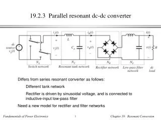
Download

1 / 16
220 likes | 471 Views
Bi-directional DC-DC converter with Soft Switching Cell. EPE-PEMC 2006, Portoroz 31 th Aug 2006. Co-ordinators: Dr. Michael G. Egan Dr. John G. Hayes. Student: Marek Ry ł ko. Topology basics. Topology Fundamentals BOOST ZCCM BUCK SS Boundary Turn ratio Duty – ideal Duty – damped

E N D
Bi-directional DC-DC converter with Soft Switching Cell EPE-PEMC 2006, Portoroz 31th Aug 2006 Co-ordinators: Dr. Michael G.Egan Dr. John G. Hayes Student: Marek Ryłko
Topology basics Topology Fundamentals BOOST ZCCM BUCK SS Boundary Turn ratio Duty – ideal Duty – damped Summary Further plans END • Introduce Soft Switching Cell • 5 extra elements • 2 aux. Switches • 2 aux. Diodes • Autotransformer Hard Switching Soft Switching
Fundamentals of operation Topology Fundamentals BOOST ZCCM BUCK SS Boundary Turn ratio Duty – ideal Duty – damped Summary Further plans END Continous conduction mode • Fixed bus-voltages • Operating frequency – above audible noise Maximum frequency limited by system topology and devices properties • Efficiency 92-98% • Hardware overcurrent protection • Main switches operates as thyristor-dual • Fully ZVCS switch-on main switches and snubber assisted switch-off • ZCS switch-on and ZVCS turn-off of auxiliaries • Main diodes reverse recovery limited by soft-switching cell inductance
Basic waveforms - BOOST Topology Fundamentals BOOST ZCCM BUCK SS Boundary Turn ratio Duty – ideal Duty – damped Summary Further plans END Main inductor current Resonant ind. current Main switch current Flywheeling diode current Pole voltage Low voltage bus current Main inductor voltage
Basic waveforms - ZCCM Zero Current Crossing Mode Topology Fundamentals BOOST ZCCM BUCK SS Boundary Turn ratio Duty – ideal Duty – damped Summary Further plans END Main inductor current Resonant ind. current Main switch current Flywheeling diode current Pole voltage Low voltage bus current
Basic waveforms - BUCK Topology Fundamentals BOOST ZCCM BUCK SS Boundary Turn ratio Duty – ideal Duty – damped Summary Further plans END Main inductor current Resonant ind. current Main switch current Flywheeling diode current Pole voltage Low voltage bus current Main inductor voltage
Soft Switching boundary Topology Fundamentals BOOST ZCCM BUCK SS Boundary Turn ratio Duty – ideal Duty – damped Summary Further plans END Pole voltage swing (boost): Minimum value is achieved for: Pole voltage must reach zero: Soft Switching boundary is:
Transformer turn ratio Topology Fundamentals BOOST ZCCM BUCK SS Boundary Turn ratio Duty – ideal Duty – damped Summary Further plans END • Presented boundary for soft switching refer to auxiliary voltage VS • Damp resistance is present Rdand take part as voltage drop • Initial conditions are significant factor when main current is large • Diodes voltage drop affect soft switching • Voltage swing must be overestimated to take into account main-switch turn-on time
Duty factor Topology Fundamentals BOOST ZCCM BUCK SS Boundary Turn ratio Duty – ideal Duty – damped Summary Further plans END Because bus voltages are fixed, the duty factor depends on main inductor current as derivative of average value of pole voltage • Hard switching (square pole voltage) • Soft switching rr= 0(deformation of rising and falling edge)
System characteristic DvsI Topology Fundamentals BOOST ZCCM BUCK SS Boundary Turn ratio Duty – ideal Duty – damped Summary Further plans END
Damped Cell – non ideal case rr ≠0 Topology Fundamentals BOOST ZCCM BUCK SS Boundary Turn ratio Duty – ideal Duty – damped Summary Further plans END • Damped cell Duty factor
System characteristic DvsI Topology Fundamentals BOOST ZCCM BUCK SS Boundary Turn ratio Duty – ideal Duty – damped Summary Further plans END
Difference between ideal and damped system Topology Fundamentals BOOST ZCCM BUCK SS Boundary Turn ratio Duty – ideal Duty – damped Summary Further plans END
Summary of soft switching system Topology Fundamentals BOOST ZCCM BUCK SS Boundary Turn ratio Duty – ideal Duty – damped Summary Further plans END • EMI improvement • Good efficiency • Decreased switching losses • Distributed heat radiation • Silent operation (over audible frequencies) • No significant volume improvement • More complex system • Gain affected due to cell operation
Further research plan Topology Fundamentals BOOST ZCCM BUCK SS Boundary Turn ratio Duty – ideal Duty – damped Summary Further plans END • Development of systems above 10kW • Compare with other bi-directional topologies • Interleaved, multiphase converters • Comparison of high ripple current and low ripple current cases • Investigation of IGBT operation in soft-switched regimes • MOSFETs in interleaved systems for high power • Inductor design • Coupled inductor approaches • Fully resonant approach • Hardware, FPGA’s for control • Conference papers
THE END Topology Fundamentals BOOST ZCCM BUCK SS Boundary Turn ratio Duty – ideal Duty – damped Summary Further plans END Thank you for your attention!