Download
1 / 16
170 likes | 186 Views
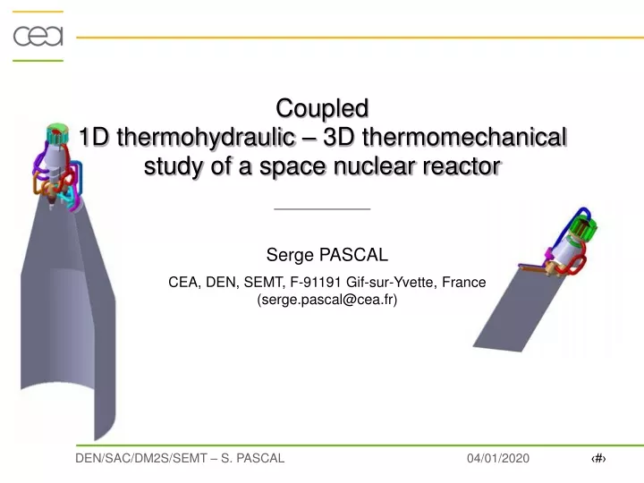
Coupled 1D thermohydraulic – 3D thermomechanical study of a space nuclear reactor. Serge PASCAL CEA, DEN, SEMT, F-91191 Gif-sur-Yvette, France (serge.pascal@cea.fr). Dispersed coated particles embedded in a ceramic matrix. Ceramic Composite. Layers. Reactor Core. Nuclear fuel elements.

E N D
Coupled1D thermohydraulic – 3D thermomechanical study of a space nuclear reactor Serge PASCAL CEA, DEN, SEMT, F-91191 Gif-sur-Yvette, France (serge.pascal@cea.fr)
Dispersed coated particles embedded in a ceramic matrix Ceramic Composite Layers Reactor Core Nuclear fuel elements Particle design The OPUS System • To maintain a waking state activity • Pre-conceptual design studies of what would be a NEP system in the range 100-500 kWeOPUS studies • Preliminary basic options • Gas-cooled reactor • Fast neutron spectrum • Dynamic conversion cycle • Basic core design • Refractory material to achieve high temperature (1300 K at the outlet) • Fast neutron spectrum to reduce the critical mass • Coated fuel particles (BISO) embedded in hexagonal graphite fuel elements Fuel
Material heterogeneity simplification • Equivalent Homogeneous Media criterion • Effective thermoelastic properties : • l*, E*, n*, a* functions of {li, Ei, ni, ai}1i n and phase proportions {ci}1i n • Local strains and stresses : avec : Composite fuel modeling* (*) E. Hervé, A. Zaoui, “N-layered inclusion-based micromechanical modelling”, Int. J. Engng Sci., 31 (1993) 1-10.
Pthparticule Tcanal L3 L1 Tcanal L2 Nuclear fuel Composite fuel modeling: validation & ongoing studies • Fuel Element cross-section modelling • Thermomechanical modelling • Results • Heterogeneous media modelling • (F. Di Paola PhD Thesis) • Mesh generation • Mechanical Characterisation Particle Volume Fraction ~ 43% Local stress and strain fields
10 30 270 480 265 z -y 10 x Geometry / Finite Element Mesh 1/12th of the Reactor Fuel elements Core binder (graphite) Contact FE mesh Pressure vessel (Nb1Zr) Coolant gas (HeXe85g/mol) Inter-element clearance: 2/10
Tinlet=880K, MF=3.8kg.s-1 Heat radiated between core & PV Thermal Power Density (MW.m-3) Heat radiated into space Tin(core)=Tout(vessel) 1D-thermohydraulic / 3D-thermal coupling Thermohydraulic: • 1D modelling: Mass conservation & Energy balance, but pressure dropneglected • He-Xe proportion parameterized • State law: ideal gas law • Boundary conditions Tinlet = 880K MFinlet = 3.8kg/s Toulet = 1300K • Convective heat exchange:Colburn or Dittus-Bolter • Nu = 0.023Re0.8Pr(1/3 or 0.4) h = Nu He(Tm)/d • Thermal: • 3D modelling:core =continuous media • Thermal loading: Power density fit to TRIPOLI results • Pth=400kW • Boundary conditions: - Convective heat exchange with the coolant gas on: Channel / outer Core / inner Pressure Vessel surfaces - Radiant heat exchange between: outer Core / inner PV surfaces & outer PV surface
Results & Evolution from 0 to 2000 EFPD Due to the decrease of thermal conductivity under irradiation : Graphite Fuel Elements Thermal conductivity Vs. Temperature & Irradiation Dose Temperature Toutlet = 1300K Temperature (K) Structures & Coolant gas
Thermohydraulic-Thermal Simulations : Summary • Main results • Tmax : 1909K 2001K (~1730°C) ! • Max. Temp. under irradiation due to Graphite Thermal Conductivity • Radiant Heat Exchange PV Temperature Gradients (DT ~20K) • Convective Heat Exchange Analogy not fully satisfying: • Experimental data onHe-Xe coolant in such conditions ? • Modelling improvements • Thermal modelling: reactor core modelled as a continuous media • but temperature jumps at the fuel element interface should be very important… • Thermohydraulic BC: mass flow prescribed at the core inlet • but coolant flow should not uniformly distributed over the channels • thermal gradients could be even more important in the core • Remark on the Simulation Tool • Temperature field of the reactor fully determined in 3D by setting only 3 parameters: • Inlet Coolant Temp. / Inlet Mass Flow / Thermal Power of the Core
Static B.C. Pressure loading applied on the red surfaces : u(z)=constant z y u(x,y)=(a.DT+eir).x x P=1,4 MPa symmetry Irradiation vol. change symmetry u(z)=0 u(x,y)=(a.DT+eir).x u(z)=constant Mechanics: Boundary Conditions and Loadings Cinematic B.C.
Mechanics: Pressure Vessel Summary • Stress state Max (sqq) ~ 41MPa ~ P.Rm /e (38.5MPa) Max (szz) ~ 23MPa ~ P.Rm/2e (19.5MPa) thermal stresses very low • Mechanical Design Static : sy ~ 110 MPa ~ smax / 3 thickness = 10 mm ~ ok • But : M(core) ~ 700kg PV design = dynamic loadings (lift-off ~ 4g)
Mechanics: Core Binder 8 with Top & Bottom Cinematic B.C. Deformed shape (x50) srr (MPa) at 0 & 2000 EFPD
Mechanics: Core Binder without Top & Bottom Cinematic B.C. Stresses (MPa) Vs. Time (EFPD) Deformed Shape : (x20) axially, (x200) in the (O,r,q ) plane
Mechanics: Reactor Core 6 Deformed Shape (x50) Difference of Axial Displacements (Core Top & Bottom)
Mechanics: Fuel Elements Problem with the Cinematic B.C. at the Fuel Element Top & Bottom (srr at 0 EFPD) Effective stress sqq in the fuel element graphite matrix Stresses (MPa) Vs. Time (EFPD)
Space Reactor Design: Main Conclusions • Thermal-Thermohydraulic • Tmax : 1909K 2001K (~1730°C) • Temperature jumps and coolant flow distribution Tmax ~ 2300 K (~ 2000°C) • To optimize channel diameter to homogenize core temperature • Temperature fieldfully determined over the reactor only by setting : • Inlet Coolant Temp. / Inlet Mass Flow / Thermal Power of the Core • Mechanics • PV: Current design satisfied nominal static loading but: • Mechanical design should more depend on dynamic loadings (lift-off) • Core Binder: Du (BC) ~ 1/10mm design ok • Fuel elements: Idem Core Binder and: • - 100 kWe OPUS version seems feasible fuel fabrication? • - 500 kWe OPUS version needs fuel design improvements
Conversion Systems Brayton cycle • He-Xe (85 g/mol) • 3.6 kg/s • DTcore = 427 °C • h = 27 % • 50 m² of radiator • 14 bars • 900 kg Hirn cycle • Sulfur, Alkali metal, … • 1 kg/s (S) • DTcore = 600 °C • h > 50 % • 7 m² of radiator • 8 bars • 620 kg 13 m Sray = 80 m² a=18 kg/kWe a=24 kg/kWe 100 kWe – 1300 K