Download
1 / 40
400 likes | 682 Views
Design and drawing of RC Structures CV61. Dr. G.S.Suresh Civil Engineering Department The National Institute of Engineering Mysore-570 008 Mob: 9342188467. Email: gss_nie@yahoo.com. DETAILING OF BEAM &SLAB. Learning out Come. Review of detailing of beams Continuous rectangular beams

E N D
Design and drawing of RC StructuresCV61 Dr. G.S.Suresh Civil Engineering Department The National Institute of Engineering Mysore-570 008 Mob: 9342188467 Email: gss_nie@yahoo.com
Learning out Come • Review of detailing of beams • Continuous rectangular beams • Cantilever rectangular beams • Flanged beams • Introduction to detailing of slab • One way slab
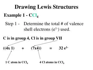
Draw the Longitudinal section and two cross sections one near the support and other near the mid span of a RCC continuous beam with the following data: Clear span of beams = 3m each Width of beam = 200mm Overall depth of beam = 300mm Width in intermediate supports = 200 mm Main reinforcement = 4 Nos -12 mm diameter bars with 2 bars bent up Anchor/hanger bars= 2-10 mm diameter Stirrups = 6 mm diameter @ 300 mm c/c. Materials : HYSD bars and M20 grade concrete • PROBLEM No. 3
A rectangular beam of cross section 300 x 450 mm is supported on 4 columns which are equally spaced at 3m c/c. The columns are of 300 mm x 300 mm in section. The reinforcement consists of 4 bars of a6 mm diameter (+ve reinforcement) at mid span and 4 bars of 16 mm diameter at all supports (-ve reinforcement). Anchor bars consists of a 2-16 mm diameter. Stirrups are of 8 mm diameter 2 legged vertical at 200 c/c throughout. Grade of concrete is M20 and type of steel is Fe 415. Draw longitudinal section and important cross sections. • PROBLEM No. 4
Draw to scale of 1:20 the Longitudinal section and two cross-section of a cantilever beam projecting 3.2 from a support using following data Clear span =3.2m Overall depth at free end = 150 mm Overall depth at fixed end = 450 mm Width of cantilever beam = 300 mm Main steel = 4-28 mm dia with two bars curtailed at 1.5m from support Anchor bars = 2 Nos. 16 mm dia Nominal stirrups = 6mm dia at 40 mm c/c Bearing at fixed end = 300 mm Use M20 concrete and Fe 415 steel • PROBLEM No. 5
A cantilever beam with 3.2m length is resting over a masonry wall and supporting a slab over it. Draw to a suitable scale Longitudinal section, two cross-sections and sectional plan with the following data: Size of beam = 300 mm x 350 mm at free end and 300 mm x 450 mm at fixed end and in the wall up to a length of 4.8m Main steel: 4 nos. of 25 mm dia bars, two bars curtailed at 1.2m from free end Hanger bars: 2 nos. 16mm. Stirrups: 6mm dia 2 legged stirrups @ 200 mm c/c the support length and @100 mm c/c from fixed end up to length of 1m @ 150mm c/c up to curtailed bars and remaining @ 200 c/c. Use M20 concrete and Fe 415 steel • PROBLEM No. 6
A beam has following data Clear span = 4m Support width = 300mm Size of web = 350 x 400 Size of flange = 1200 x 120mm Main reinforcement in two layers : 3-20 tor + 3-16 tor and to be curtailed at a distance 400 mm from inner face of support Hanger bars: 3- 20 tor Stirrups: 2L-8 tor @ 200 c/c Use M20 concrete and Fe 415 steel Draw longitudinal and cross section if the beam is T-beam Inverted T-beam L-Beam • PROBLEM No. 7
Dr.G.S.Suresh Introduction • Used for covering spaces in the form of roof or floor • Slab may be supported on walls or beams or columns. • Slab supported directly by columns are called flat slab • One Way Slab • Two Way Slab
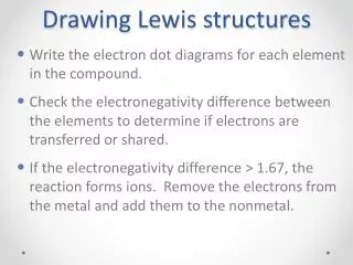
Dr.G.S.Suresh Introduction • Slabs could be simply supported, continuous or cantilever • In two way slab the corners may be held down by restraints or may be allowed to lift up • Additional torsion reinforcement is required at corners when it is restrained against uplifting as shown in Fig
Dr.G.S.Suresh Introduction
Dr.G.S.Suresh Introduction • Thickness of the slab is decided based on span to depth ratio specified in IS456-2000. Min reinforcement is 0.12% for HYSD bars and 0.15 % for mild steel bars. • The maximum diameter of bar used in slab should not exceed 1/8 of the total thickness of slab • Maximum spacing of main bar is restricted to 3 times effective depth or 300 mm which ever is less • For distribution bars the maximum spacing is specified as 5 times the effective depth or 450 mm which ever is less
Dr.G.S.Suresh Introduction • Generally 15 mm to 20 mm cover is provided for the main reinforcements • Alternate main bars can be cranked near support or could be bent at 1800 at the edge and then extended at the top inside the slab as shown in Fig • Curtailment and cranking of bars and is shown in Fig
Dr.G.S.Suresh Introduction
Dr.G.S.Suresh Introduction • Torsion Reinforcement shall be provided as shown in Fig.
Dr.G.S.Suresh Torsion Reinforcement
Dr.G.S.Suresh Torsion Reinforcement
Dr.G.S.Suresh Typical One Way slab
Dr.G.S.Suresh Typical Two Way slab
Prepare a detailed structural drawing of one way continuous slab for a hall of clear dimensions 7m wide and 11.77 m long, use following data Centre to centre distance of supporting beams = 3.0 m Span of the beams = 7.23m Beams are supported on walls of 0.23 m thickness C/s of beam = 230 x 450 mm Grade of concrete : M20 Type of steel : Fe415 Clear cover : 20 mm Slab thickness: 150 mm Beam depth is inclusive of slab depth, The hall is having walls on all 4 sides • PROBLEM
Main positive reinforcement @ end span = 8mm diameter @100 c/c Main reinforcement in other interior panels = 8 mm diameter @ 200 c/c Negative reinforcement @ all supports = 8mm diameter @ 200 c/c Distribution steel= 8mm diameter @ 200 c/c • PROBLEM
1. Draw the longitudinal section and typical cross sections ( at centre and support), and show the reinforcement details in a simply supported rectangular beam of size 300 mm x 500 mm, clear span 5m supported on walls of 0.3m, use a suitable scale Reinforcements: Main: 4 No. 16mm dia with 2 No. cranked at 1m from centre of support. Stirrup holders 2 Nos. of 12 mm dia Stirrups: 2 legged 8 mm dia stirrups at 250 mm c/c in the central 2m span and 2 legged 8 mm dia stirrups at 150 mm c/c in the remaining portion. Assume concrete M 20 grade and steel Fe 415, and suitable cover. Prepare the bar bending schedule and calculate quantity of steel and concrete required. • Do it Yourself
2. Prepare the bar bending schedule and estimate quantity of steel and concrete after drawing the longitudinal and cross section. Other details are Span of beam = 4.2 m Cross section at support end 300 x 600 mm and cross section at free end 300 x 150 mm Reinforcements: Main tension steel: 4-20 mm dia, 2 bars are curtailed at a distance of 2m from free end Hanger bars: 1-12 mm dia Two legged stirrups 8mm dia @ 140 mm c/c for full length. • Do it Yourself
GOOD DAY Dr. G.S.Suresh Civil Engineering Department The National Institute of Engineering Mysore-570 008 Mob: 9342188467 Email: gss_nie@yahoo.com