Download
1 / 21
220 likes | 387 Views
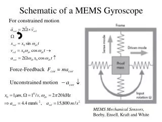
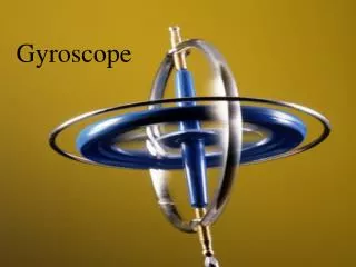
A Bond-Graph Representation of a Two-Gimbal Gyroscope. Robert T. Mc Bride Dr. François E. Cellier Raytheon Missile Systems, University of Arizona Tucson, Arizona Tucson, Arizona. ABSTRACT.

E N D
A Bond-Graph Representation of a Two-Gimbal Gyroscope Robert T. Mc Bride Dr. François E. Cellier Raytheon Missile Systems, University of Arizona Tucson, Arizona Tucson, Arizona
ABSTRACT The purpose of this paper is to show, by example of a two-gimbal gyroscope, a method for developing a bond-graph representation of a system from the Lagrangian. Often the Lagrangian of a system is readily available from texts or other sources. Although the system equations can be derived directly from the Lagrangian there is still benefit in viewing the system in bond-graph representation. Viewing the power flow through the system gives insight into the inter-relationships of the state variables. This paper will give an example where the possibility of reducing the order of the system is obvious when viewing the system in bond-graph representation yet is not readily apparent when looking at the Lagrangian or the equations derived from the Lagrangian.
Summary of the Method. • Note the flow terms in the Lagrangian. • Derivate each of the terms of the Lagrangian with respect to time. • Use bond-graph representation to complete the algebra of the equations derived above. • All of the terms of the bond-graph are now present but further connections may be necessary to complete the bond-graph. These connections will be apparent by inspecting the terms of the Lagrange equations that are not yet represented by the bond-graph.
The cross terms have not yet been represented in the bond-graph above.
Conclusions • The information contained in the Lagrangian of the two-gimbal gyroscope can be used directly to obtain a bond-graph formulation of the system. • The two-gimbal gyroscope bond-graph obtained in this paper provides a more compact construction than the bond-graph given by Tiernego and van Dixhoorn. The advantage that the Tiernego/van Dixhoorn representation has is one of symmetry in that the Eulerian Junction Structure (EJS) appears explicitly. • A reduction in the state space of the gyroscope is possible by setting the effort source SE6, and the initial condition of P3, to zero. This reduction of order comes by direct inspection of the bond graph, yet is not readily apparent from the Lagrange equations. • The simulation results for the Lagrange method and for the bond-graph are identical, baring small numerical differences. This result is fully expected since the bond-graph was obtained directly from the Lagrange equations.