Download
1 / 22
331 likes | 845 Views
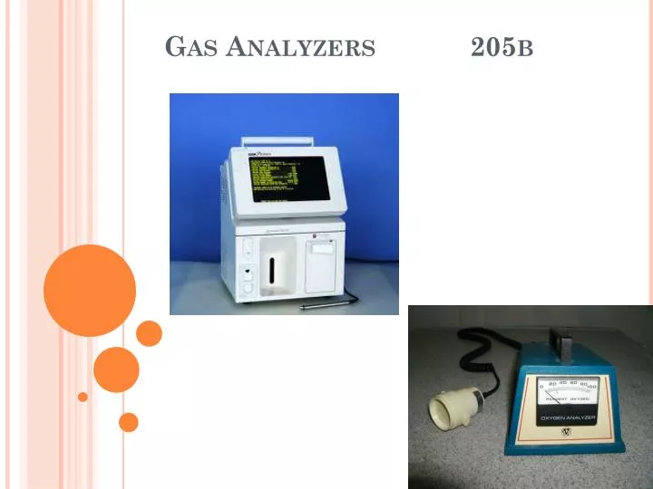
Gas Analyzers 205b. Blood Gas Analyzers Key Components. Blood Gas Analyzers consist of a 3 electrode system pH Electrode PCO 2 Electrode PO 2 Electrode Calibrating gas tanks Reagent containers containing buffers used for calibration and rinse solutions Waste containers

E N D
Blood Gas Analyzers Key Components • Blood Gas Analyzers consist of a 3 electrode system • pH Electrode • PCO2 Electrode • PO2 Electrode • Calibrating gas tanks • Reagent containers containing buffers used for calibration and rinse solutions • Waste containers • Results display, storage and transmittal systems
The PH Electrode and the Potentiometric Method • Consists of 2 half cell electrodes. • Measuring electrode • Reference electrode Measuring half cell contains a silver-silver chloride rod surrounded by a solution of fluid with a constant ph of 6.840 and is capped by a pH sensitive glass membrane The reference electrode contains a mercury/mercurous chloride rod Surrounded by a solution of potassium Chloride which creates a small electric voltage
PH Electrode • The Reference electrode creates a known voltage • The pH sensitive glass in the measuring electrode comes into contact with the blood. • H ions in the blood diffuse into the measuring electrode thru the glass • The difference in H ions on either side of the glass changes the potential charge within the measuring electrode • This change in voltage is compared with the reference electrode and converted into a pH reading. • The potential difference in current between the 2 electrodes creates the pH reading thus the name “Potentiometric Method” + +
The PO2 Electrode and the Polarographic method • The most common oxygen electrode used in blood gas analysis is the Clark Electrode.
The PO2 Electrode and the Polarographic method • Blood is separated from the electrode terminals by the use of an O2 permeable membrane • Oxygen diffuses easily thru this membrane into the electrolyte solution • The Cathode attracts oxygen molecules where they react with the H2O in the electrolyte solution • The chemical reaction at the cathode consumes 4 O2 electrons which are rapidly replaced as the silver and chloride react at the Anode. The more electrons consumed, the greater the electron flow between the poles. • The current generated will be in direct proportion to the amount of dissolved oxygen present at the cathode • A Polarogram graph shows the direct relationship between the PO2 and the voltage at the cathode Polarogram Amps PO2 (mmHg)
The Severinghaus PCO2 Electrode • Differences: • 1. Blood does not come into contact • with the pH sensitive glass. • 2. Blood comes into contact with a CO2 • permeable membrane • 3. On the other side of the membrane is • bicarbonate solution that is in direct • contact with the pH-sensitive glass • 4. A hydrolysis reaction occurs within the • bicarbonate solution as CO2 diffuses in. • 5. This reaction results in the • production of H Ions and a pH change • of the bicarbonate solution. • 6. The pH change is in direct proportion • to the PCO2, thus the corresponding • voltage change can be converted into • PCO2 units Modified version of the pH electrode +
Oxygen Analyzers Used to analyze the FiO2 of inspired gas There are 2 common types: Clark Electrode (Polarographic) Galvanic Fuel Cell Galvanic fuel cell analyzer Clark Electrodes: Function is similar to ABG machines Galvanic fuel cells use a gold anode and a lead cathode. Current is generated by the chemical reaction of potassium hydroxide and oxygen. The greater the oxygen, the more reaction with the potassium, the more current generated which is converted to %O2. Once the potassium is consumed, the fuel cell must be replaced. The fuel cell is covered when not in use, and placed proximal to any humidification device. Oxygen analyzers must be calibrated using R/A and 100% O2
Oximetry Oximetry first described in 1932 Oximetry is the measurement of hemoglobin saturation using spectrophotometry. Oximetry works because every substance emits its own unique pattern of light (absorption/emission). Each form of hemoglobin (e.g., HbO2, HbCO) has its own pattern of light absorption. For example, HbO2 absorbs less red light and more infrared light. An oximeter is an instrument that measures the amount of light transmitted through, or reflected from a sample of blood at two or more specific wavelengths.
Pulse Oximetry • A convenient, portable, continuous and non-invasive method of determining SpO2 • The pulse oximeter uses light absorption patterns to indicate saturation levels of the “pulsed” blood which is arterial blood. • Is a Trending/Monitoring device, Not a Diagnostic Tool. • Is adversely affected by: • High ambient light • Painted/false/long fingernails • Movement • Decreased local or systemic perfusion • Can be adversely affected by Hb variants: HbCO, Methemoglobin • Can be affected by vascular dyes (Methylene Blue, Indocyainie Green, Indigo Carmine) • Needs to be correlated with the HR or HR plethysmography and patient clinical appearance • Does not measure CaO2 or PCO2; patients suspected of having O2transport issues or hypoventilation should have an ABG
CO-Oximetry • Measures: • SaO2%, MetHb, HbCO% • SaO2 is measured as a percentage of the Oxyhemoglobin compared with all measured forms of Hb including dyshemoglobin species (functional Hb) • Potential measurement errors occur in neonates with substantial quantities of fetal hemoglobin - May show increased levels of HbCO, decreased SaO2 • Usually run in tandem with arterial ABGs
Transcutaneous oxygen andCO2 monitoring • Provides continuous and non invasive estimates of arterial PO2 and PCO2 through a surface skin sensor. • Expressed as PtcO2 and PtcCO2 • Devices heat the skin to help vascularize the tissue increasing the permeability of O2 and CO2 from the capillary bed
Transcutaneous oxygen andCO2 monitoring • Indications: • Continuous monitoring of adequacy of oxygenation/ventilation • Need for real time assessment of therapeutic interventions • Contraindications: • Patients with poor skin integrity and adhesive allergies • Precautions: • False-negative or false-positive results may lead to inappropriate treatment • Tissue injury (burns/tearing) may occur at the sensor site because sensor heats to 43.5 C O
Transcutaneous oxygen andCO2 monitoring • Factors affecting accuracy: • Patient age: agreement between sensed gas and actual PaO2 or PaCO2 decreases with age. The best correlation occurs only in neonates. • Poor perfusion either localized or systemic. • Calibration must be done prior to application. • Response time: response time of the electrode varies due to skin thickness, temperature and patient age
Capnometry • Term capnometry comes from the Greek word KAPNOS, meaning smoke. • Measures end tidal CO2: The maximum partial pressure of CO2 exhaled during a tidal breath just before the beginning of inspiration; expressed as PetCO2 • Respiratory context: inspired and expired gases sampled at the Y connector, mask or nasal cannula. • Gives insight into alterations in ventilation, cardiac output, distribution of pulmonary blood flow and metabolic activity. • Capnography is the technique of displaying CO2 measurements as waveforms (capnograms) throughout the respiratory cycle
2 Techniques for Monitoring PETCO2 • Two methods in obtaining a gas sample for analysis • Mainstream • Sidestream • Mainstream (Flow-through or In-line) • Adapter placed in the breathing circuit • No gas is removed from the airway • Adds bulk to the breathing circuit • Electronics are vulnerable to mechanical damage
2 Techniques for Monitoring pETCO2 • Sidestream (aspiration) • Gas is aspirated from an airway sampling site and transported through a tube to a remote CO2 analyzer • Provides ability to analyze multiple gases • Can be used in non-intubated patients • Potential for disconnect or leaks giving false readings • Withdraws 50 to 500ml/min of gas from breathing circuit (most common is 150-200ml/min) • Water vapor from circuit condenses on its way to monitor • A water trap is usually interposed between the sample line and analyzer to protect optical equipment
Location of Sensor • The location of the CO2sensor greatly affects the measurement • Measurement made further from the alveolus can become mixed with fresh gas causing a dilution of CO2 values and rounding of the capnogram
Mainstream Sidestream
How ETCO2 Works • Photo detector measures the amount of infrared light absorbed by airway gas during inspiration and expiration • CO2 molecules absorb specific wavelengths of infrared light energy • Light absorption increases directly with CO2 concentration • A monitor converts this data to a CO2 value and a corresponding waveform (capnogram)
Capnometry (cont.) The normal capnogram shows an PCO2 of zero at the start of the expiratory breath. Soon afterward, the PCO2 level rises sharply and plateaus as alveolar gas is exhaled. The end-tidal PCO2 (PETCO2) can be used to estimate deadspace ventilation and normally averages 1 to 5 mm Hg less than PaCO2 A-B Deadspace B-C Mixed airway/alveolar gas C-D Alveolar gas D-E Inspiration
Colorimetric Co2 Analyzers • Used to detect CO2 in exhaled gases • Simple, inexpensive, inline detector especially useful for detection of successful intubations • Color is purple when CO2 is less than 0.5% • Color is tan when CO2 is Up to 2% • Color is yellow when CO2 exceeds 2% • If patient has no perfusion, ET could be in airway and color will still be purple