Download
1 / 47
590 likes | 1.16k Views
VHDL 5 FINITE STATE MACHINES (FSM). Some pictures are obtained from FPGA Express V HDL Reference Manual, it is accessible from the machines in the lab at /programs/Xilinx foundation series/VDHL reference manual

E N D
VHDL 5. FSM ver.2a VHDL 5FINITE STATE MACHINES (FSM) Some pictures are obtained from FPGA Express VHDL Reference Manual, it is accessible from the machines in the lab at /programs/Xilinx foundation series/VDHL reference manual /programs/Xilinx foundation series/foundation project manager/foundation help content/XVDHL compiler help pages
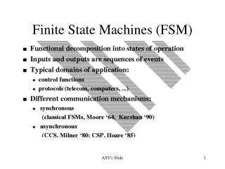
VHDL 5. FSM ver.2a Contents: You will learn • Finite state machines FSMs • Feedback using signals or variables • Use of clocks, processes to make FSMs • Different types of Finite State Machines • Moore • Mealy
VHDL 5. FSM ver.2a Finite State machines FSM • A system jumps from one state to the next within a pool of finite states upon clock edges and input transitions. (traffic light, digital watch, CPU).
VHDL 5. FSM ver.2a TO WRITE CLOCK EDGES Using if-then-else
VHDL 5. FSM ver.2a Clock edges:Use of “if Statements” or “Wait until” to represent Flip-flops • Test for edge of a signal. • if SIGNAL’event and SIGNAL = ’1’ -- rising edge • if SIGNAL’event and SIGNAL = ’0’ -- falling edge • Or • In a wait statement, edge can also be • wait until CLK = ’1’; -- rising edge triggered • wait until CLK = ’0’;--falling edge triggered
VHDL 5. FSM ver.2a Use of ‘Wait’ and ‘If’ for clock edge detection
VHDL 5. FSM ver.2a Clock edges:compare wait and if Statements • IEEE VHDL requires that a process with a wait statement must not have a sensitivity list. • In general, the following guidelines apply: • Synchronous processes (processes that compute values only on clock edges) must be sensitive to the clock signal. Use wait-until or if. • When Wait is used: The first statement must be wait until, E.g. • Process no sensitivity list, implies there is one clock as input • Begin • Wait until clock =‘1’ • Asynchronous processes (processes that compute values on clock edges and when asynchronous conditions are TRUE) must be sensitive to the clock signal (if any), and to inputs that affect asynchronous behavior. Use “if” only. • E.g. Process (clock, input_a, input_b…)
VHDL 5. FSM ver.2a THE FEEDBACK CONCEPT For making FSM
VHDL 5. FSM ver.2a The feedback concept • So far you learned logic with feed forward paths only. • Now, you will see feedback paths. • The first step of the making a state machine
VHDL 5. FSM ver.2a Feedback 1 -- direct feedback • 1 architecture example of some_entity is • 2 -- • 3 begin • 4 process(clk,reset) • 5 begin • 6 if reset = '1' then c <= '0'; • 7 elsif rising_edge(clk) • 8 then c<= not(a and c); • 9 -- • 10 end if; • 11 end process; • 12 end example; -- synthesized ok b Q D c a Clock clk reset reset If C is an IO pin connected outside, it must have type inout or buffer
VHDL 5. FSM ver.2a Concentrate on line 7-8 of Feedback 1 Use of signals in a clocked process • 7 elsif rising_edge(clk) • 8 then c<= not(a and c); • ****************Note *********** • Current not(a and c) affects next b
VHDL 5. FSM ver.2a b Q Worksheet 5.1 D c a Clock clk • Initially c=0 • Draw c reset Clock Reset a c reset
VHDL 5. FSM ver.2a Feedback 2 -- using signals • 1 architecture example of some_entity is • 2 signal b: std_logic; -- b is global, • 3 begin • 4 process(clk,reset) • 5 begin • 6 if reset = '1' then c <= '0'; • 7 elsif rising_edge(clk) • 8 then b<= not(a and c); • 9 c <= b; • 10 end if; • 11 end process; • 12 end example; -- synthesized ok b2 b1 q D q D a c Clock clk reset reset If C is an IO pin connected outside, it must have type inout or buffer
VHDL 5. FSM ver.2a Concentrate on line 7-8 of feedback 2Use of signals in a clocked process • 8 then b<= not(a and c); • 9 c <= b; • ****************Note *********** • Current {not (a and c)} affects next b • Previous (before 8 is executed) b affects c • The two b’s in the process have different states
VHDL 5. FSM ver.2a b2 b1 q Exercise 5.2 D q D a c Clock clk • Initially c=0,b1=1,b2=1 • Draw b2,c reset Clock reset a b1 b2 c reset
VHDL 5. FSM ver.2a Feedback 3 -- using variables • 1 Process -- no sensitivity list for ‘wait unit’ • 2 variable v: std_logic; --v is local • 3 begin • 4 wait until clk = '1'; • 5 if reset = '1' then v := '0'; • 6 else v := not (a and c); • 7 c <= v; • 8 end if; • 9 end process; • -- synthesized ok v Q a D c Clock clk reset reset If C is an IO pin connected outside, it must have type inout or buffer
VHDL 5. FSM ver.2a Concentrate on line 6-7 of feedback 3Use of signals in a clocked process • 6 else v := not (a and c); • 7 c <= v; • ****************Note *********** • Current not(a and c) affects next variable v • The new variable (after line6 is executed) v affects c • This is the main difference between signal and variable in a clocked process • Signals do not change immediately • Variables change immediately
VHDL 5. FSM ver.2a v Q Exercise 5.3 a D c Clock clk • Initially c=0 • Draw c reset reset Clock Reset a c
VHDL 5. FSM ver.2a Use of object types inout and buffer in feedback • Buffer can be read back • inout allows for internal feedback, it can also read external signals. in out buffer in Inout in out
VHDL 5. FSM ver.2a Important: Feedback using signals and variables will give different results. • Variable: A variable in a process can update many times. • Signal: • “<= ” can be treated as a flip-flop • (left side of “<= ” is output, right side of “<= ” is input) , it only updates once when the process executes at the triggering clock edge. • When a signal is assigned to different values by different statements in a process, only the last statement is effective.
VHDL 5. FSM ver.2a Inside a process The Trick!! • Signals in a process: • Combination process=the process has no clock edge detection: only the last assignment statement for that particular signal counts, the assignment is a combinational logic circuit. • Clocked process=the process has clock edge detection (e.g. if rising_edge(clk) ) • Signal assignment before clock edge detection: same as combination processes (same as above). • Assignment after clock edge detection: the assignment is a flip-flop. • Variables in processes (only live in processes anyway): when all signals are stable, then use your old programming common sense. Assignments take effect immediately.
VHDL 5. FSM ver.2a EXAMPLE TO SHOW The difference between signal and variables in feedback processes
VHDL 5. FSM ver.2a (page 6-9 xilinx foundation4.2 vhdl reference) signal S1, S2: BIT; -- signal S_OUT: BIT_VECTOR(1 to 8); • process( S1, S2 ) • variable V1, V2: BIT; • begin • V1 := ’1’; -- This sets the value of V1 • V2 := ’1’; -- This sets the value of V2 • S1 <= ’1’; -- This assignment is the driver for S1 • S2 <= ’1’; -- This has no effect because of the • -- assignment later in this process • S_OUT(1) <= V1; -- Assigns ’1’, the value assigned above • S_OUT(2) <= V2; -- Assigns ’1’, the value assigned above • S_OUT(3) <= S1; -- Assigns ’1’, the value assigned above • S_OUT(4) <= S2; -- Assigns ’0’, the value assigned below • V1 := ’0’; -- This sets the new value of V1 • V2 := ’0’; -- This sets the new value of V2 • S2 <= ’0’; -- This assignment overrides the • -- previous one since it is the last assignment to this signal here • S_OUT(5) <= V1; -- Assigns ’0’, the value assigned above • S_OUT(6) <= V2; -- Assigns ’0’, the value assigned above • S_OUT(7) <= S1; -- Assigns ’1’, the value assigned above • S_OUT(8) <= S2; -- Assigns ’0’, the value assigned above • end process;
VHDL 5. FSM ver.2a • (See VHDL reference manual version : chapter 6 [sequential statements]: variable/signal assignment statements.) • signal S1, S2: BIT; • signal S_OUT: BIT_VECTOR(1 to 8); • . . . • process( S1, S2 ) • variable V1, V2: BIT; • begin • V1 := ’1’; -- This sets the value of V1 • V2 := ’1’; -- This sets the value of V2 • S1 <= ’1’; -- This assignment is driver for S1 • S2 <= ’1’; -- This has no effect because of the • -- assignment later in this process
VHDL 5. FSM ver.2a • S_OUT(1) <= V1; -- is ’1’, the value assigned above • S_OUT(2) <= V2; -- is ’1’, the value assigned above • S_OUT(3) <= S1; -- is ’1’, the value assigned above • S_OUT(4) <= S2; -- is ’0’, the value assigned below • V1 := ’0’; -- This sets the new value of V1 • V2 := ’0’; -- This sets the new value of V2 • S2 <= ’0’; -- This assignment overrides the • -- previous one since it is the last • -- assignment to this signal in this • -- process
VHDL 5. FSM ver.2a • S_OUT(5) <= V1; -- is ’0’, the value assigned above • S_OUT(6) <= V2; -- is ’0’, the value assigned above • S_OUT(7) <= S1; -- is ’1’, the value assigned above • S_OUT(8) <= S2; -- is ’0’, the value assigned above • end process;
VHDL 5. FSM ver.2a Examples:signals and variables in process( )See Roth p.66 • Process --a variable can change value many times in a process • variable v1: integer :=1; --initialized to1 • variable v2: integer :=2; --initialized to 2 • variable v3: integer :=3;--iniltialized to 3 • begin wait on trigger; • --find results after clock edge--------------- t1 t2 t3 t4 • v1:=v2+v3; -- after t1, now v1 = 2+3=5 5 10 20 40 • v2:=v1; -- after t1, now v2=5 5 10 20 40 • v3:=v2; -- after t1, now v3=5 5 10 20 40 • sum<=v1+v2+v3; 15 30 60120 • -- so sum=5+5+5=15 after the first trigger clock edge. • end process Variables case
VHDL 5. FSM ver.2a Signal case • Exercise 5.4:Architecture sig_arc of example is • signal s1: integer:=1; • signal s2: integer:=2; • signal s3: integer:=3; • begin -- t1 is just after the first clk edge, etc • process begin wait on clk;-- t1 t2 t3 t4 • s1<=s2+s3; -- s1= • s2<=s1; -- s2= • s3<=s2; -- s3= • sum<=s1+s2+s3;--sum= • end process • end __ __ __ __ __ __ __ __ __ __ __ __ __ __ __ __
VHDL 5. FSM ver.2a • library IEEE; -- successfully compiled and tested. In Xilinx, init. signals cannot be done • use IEEE.STD_LOGIC_1164.all; -- so use reset to set them to init values • use IEEE.std_logic_arith.all; • use IEEE.std_logic_unsigned.all; • entity some_entity is • port ( clk : in STD_LOGIC; • reset : in STD_LOGIC; • sportsum: out integer); • end some_entity; • Architecture sig_arc of some_entity is • signal t1, t2, t3 : integer; -- In Xilinx, ini. Signals cannot be done • begin -- t1 is just after the first clk, etc • --with clk, without clk, with s1234, in sen. list or not • process(clk,reset) -- clocked process, syn. input can be in or not in the sensitivity list • -- begin wait on clk;-- t1 t2 t3 t4 • begin if reset = '1’ then -- use reset to set them to init values • t1 <= 1; • t2 <= 2; • t3 <= 3; • sportsum <= 0; • elsifclk='1' and clk'event then • t1<=t2+t3; -- s1= • t2<=t1; --s2= • t3<=t2; --s3= • sportsum <= t1+t2+t3; -- sum= 6, 8, 9, 14 after each clock edge • end if; end process; • end sig_arc;
VHDL 5. FSM ver.2a • --test the use of signals and variables for feedback • library IEEE; --project testfd2 • use IEEE.STD_LOGIC_1164.all; • library METAMOR; • use METAMOR.attributes.all; • library SYNOPSYS; • use SYNOPSYS.std_logic_arith.all; • use SYNOPSYS.std_logic_unsigned.all; • --library IEEE; -- feedback 1 example ,-- synthesized ok. • --use IEEE.std_logic_1164.all;
VHDL 5. FSM ver.2a Plot result. Try this in lab and explain the result • Exercise 5.5: architecture example of some_entity is • signal con1: std_logic; -- b is global, bit is a VHDL type • begin • process(clk,reset) • variable v1: std_logic; • begin • if reset = '1' then out1 <= '0'; out2<='0'; out3<='0';con1<='1'; • elsifrising_edge(clk) then • ---case 1 ----- direct feedback • out1<= not(in1 and out1); -- out1 is immediate • ---case 2 ----- feedback using signal • con1<= not(in1 and out2); • out2<= con1; -- out2 is delayed hence lower frequency • ---case 3 ----- feedback using variable • v1:=not(in1 and out3); -- out3 is immediate • out3 <= v1; • end if; end process; end example; -- synthesized
ex5 vhdl ver 2.1c Worksheet 5.5 Clock Reset Out1 Out2 Out3 Con1
FSM Moore machine Mealy machine Types of FSM Finite State machines-Study FSMs with inputs other than the clock VHDL 5. FSM ver.2a
VHDL 5. FSM ver.2a State machine designs, 2 types • A Moore machine’s outputs are a function of the present state only. • A Mealy machine’s outputs are a function of the present-state and present-inputs.
not Nand D type FF VHDL 5. FSM ver.2a Moore machine, an example F1 is B<= not (A and C)F2 is D<= not C • Output is a function of the state registers. • The simplest Moore machine use only one process , see next page
VHDL 5. FSM ver.2a Moore machine example1architecture moore2_arch of system is2 signal C: bit; -- global, can be seen by different • 3 begin • 4-- since D is purely for output, no feedback read • 5 -- requirement, so it has the type out • 6 D <= not C; -- F2 = combination logic • 7-- • 8 process -- sequential logic • 9 begin • 10 wait until clock; • 11 C <= not (A and C); --F1 = combination logic • 12 end process; • 13 end moore2_arch; process :F1
VHDL 5. FSM ver.2a • library IEEE; -- Moore2 machine example ,(complete program) • use IEEE.std_logic_1164.all; • entity system is • port ( • clock: in boolean; • A: in STD_LOGIC; • D : out STD_LOGIC ); • --since D is purely for output, no feedback read requirement, so it has the type out • end system; • architecture moore2_arch of system is • signal C: std_logic; • begin • D <= not C; -- F2 = combination logic • process -- sequential logic • begin • wait until clock; • C <= not (A and C); --F1 = combination logic • end process; • end moore2_arch ;
VHDL 5. FSM ver.2a Moore machine using 2 processes • It is more flexible and easier to design. • You can make it formal that F1 is a process and • F2 is another process
VHDL 5. FSM ver.2a Moore machine1architecture moore2_arch of system is2 signal C: bit; -- global, can be seen by different process :F2 • 3 begin • 4 process (C) -- combinational logic • 5 begin • 6 D <= not C; -- F2 = combination logic • 7 end process; • 8 process -- sequential logic • 9 begin • 10 wait until clock; • 11 C <= not (A and C); --F1 = combination logic • 12 end process; • 13 end moore2_arch; process :F1
VHDL 5. FSM ver.2a • library IEEE; -- Moore2 example ,-- synthesized ok. • use IEEE.std_logic_1164.all; • entity some_entity is • port ( • clock: in Boolean; • A,reset: in bit; • D: out bit -- no need to use inout or buffer type, since there is no need to read. • ); • end some_entity; • architecture moore2_arch of some_entity is • signal B,C: bit; • begin • process (C) -- combinational logic • begin • D <= not C; -- F2 = combination logic • end process; • process -- sequential logic • begin • wait until clock; • C <= not (A and C); --F1 = combination logic • end process; • end moore2_arch;
VHDL 5. FSM ver.2a Exercise 5.6 ,exercise on Moore machine, draw c (init. c=0) • clock C=/D when A=1 C=/D when A=0 not Nand D type FF
VHDL 5. FSM ver.2a Mealy machine • A Mealy machine’s outputs are a function of the present state and the inputs.
D Q D-Flip-Flop or Nor VHDL 5. FSM ver.2a Mealy machine, an example • A Mealy Machine can use two processes, since its timing is a function of both the clock and data inputs. • F1 is B <= not(AorC); F2 is D <= (A or C)
VHDL 5. FSM ver.2a Mealy machine use processes1 architecture mealy of system is 2 signal C: bit; • 3 begin • 4 process (A,C) -- combinational logic process • 5 begin • 6 D <= (A or C);--F2 = combination logic • 7 end process; • 8 process -- sequential logic process • 9 begin • 10 wait until clock=‘1’; • 11 C <=not(A orC);--F1 = combination logic • 12 end process; • 13 end mealy; process :F2 process :F1
VHDL 5. FSM ver.2a • library IEEE; -- Mealy example ,-- synthesized ok. • use IEEE.std_logic_1164.all; • entity some_entity is • port ( • clock: in Boolean; • A,reset: in bit; • D: out bit -- no need to use inout or buffer type, since there is no need to read • ); • end some_entity; • architecture mealy_arch of some_entity is • signal C: bit; • begin • process (A,C) -- combinational logic process • begin • D <= (A or C);--F2 = combination logic • end process; • process -- sequential logic process • begin • wait until clock; • C <=not(A or C);--F1 = combination logic • end process; • end mealy_arch;
D Q D-Flip-Flop or Nor VHDL 5. FSM ver.2a Exercise 5.7: on Mealy machine, Plot C,D (init. c=0) clock • F1 is B <= not(A or C); F2 is D <= (A or C) A C D
VHDL 5. FSM ver.2a Quick revision • You should know • How to write a clock edge detector • Feedback theory and implementation • Design Moore and Mealy machine • Use of signal and variables and understand their differences