Download
1 / 23
230 likes | 329 Views
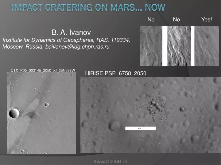
No No Yes!. B. A. Ivanov Institute for Dynamics of Geospheres, RAS, 119334, Moscow, Russia, baivanov@idg.chph.ras.ru. CTX_P05_003145_2050_XI_25N098W. HiRISE PSP_ 6758_2050. Impact cratering on Mars… Now.

E N D
No No Yes! B. A. Ivanov Institute for Dynamics of Geospheres, RAS, 119334, Moscow, Russia, baivanov@idg.chph.ras.ru CTX_P05_003145_2050_XI_25N098W HiRISE PSP_6758_2050 Impact cratering on Mars… Now October 2010 1MS3-1-3
HiRISE resolution from 25 to 30 cm/pixel allows us recognize small craters with D≥ 1.5 m • Main attention is devoted to young small craters with the age of 10 years and younger. • 19 of 20 young craters from Malin’s collection (Malin M.C. et al. ,2006, Science, 314, 1573-1577) are confirmed • Now the list of dated (“new”) small craters has more than 140 candidates • Data processing is finished for ~140 cases • About 50% of impacts create clusters of craters October 2010 1MS3-1-3
Martian atmosphere Atmospheric density at 15 km altitude is the same as at 40 km above the Earth surface. Projectiles making bolides on Earth, are able to record themselves making craters on Mars October 2010 1MS3-1-3
Welcome the Town of Young Craters! • Location: dusty areas on Mars (where easy to find) • Population: from 1 to 3000 individual craters in a cluster (clustered and single crater cases are ~50/50) • Altitude: from -6km to +18 km (in respect to the smoothed areoid surface) • Maximum size to date: D~35 m (ND>31.25 =3) October 2010 1MS3-1-3
Location of new craters October 2010 1MS3-1-3
Almost all new impact sites found over dusty areas October 2010 1MS3-1-3
Smallest new crater (~2.5 m) formed between April 2006 and February 2008 (ESP_016660_1860) Largest new crater (54m) October 2010 1MS3-1-3 Not all craters are as simple …
Atmospheric breakup Passey&Melosh, 1980, Icarus 42 (2), 211-233 PSP_09185_1770 Ellipse 137x37 m Apparent angle ~15o 0.5 vT v Z/sin 0.5 vT Z Ellipse: 2a = r/sin , 2b=r PPT=Plane Perpendicular to Trajectory Circle: 2 r = vT *tflight October 2010 1MS3-1-3
Minimum altitude: size 7 m, population N>49 Cluster at lowermost altitude (Hellas): h=-6.36 km (PSP_007596_1295) Dmax ~ 5.2 m rm~3000 kgm-3 Z~ 3 km (+6 km below zero) s10 ~11 bar October 2010 1MS3-1-3
Maximum altitude of 18 km: size 5 m, population N>23 New Impact Site Formed between November 2007 and February 2009 (ESP_013707_1915) <r> =42 m, Dmax ~ 3.2 m October 2010 1MS3-1-3
Single fragmentation • Shock wave interaction gives small transversal velocity vT to fragments • CT ~ 0.9 (derived from the numerical modeling) corresponds to separation of craters on surface of the order of 30 to 50 m on Mars • Atmospheric density at the fragmentation point defines stagnation pressure at the breakup, proportional to the effective strength • a v2 • The final separation radius in PPT is a function of Z with a maximum at ~22 km on Mars (at v=10 km/s s ~ 2 bar – similar to Earth bolides) 0.5 vT 0.5 vT October 2010 1MS3-1-3 ArtemievaA&Shuvalov, JGR106, 3297-3310, 2001
Three levels of modeling • Geometrical modeling: assumes one craters-one fragment, takes care only about location of craters with a weak role of the fragment (crater) size. Gives quick estimates of break up parameters • Analytical solution to fragment deceleration with a constant ablation coefficients (recognizes ice, CC, OC, and iron meteoroids) • Direct 3D modeling of each fragment atmospheric passage with the ablation • ##2 and 3 needs to assume a scaling law for crater sizes. Currently we use porous (dry sand) scaling with a possibility to have strength-to-gravity transition for D=1 to 10 m. Loose dust? How thick? What is the substrate? • Projectile sizes for our crater collection is below ~2 m in diameter October 2010 1MS3-1-3
Cascade fragmentation The first fragmentation event happened at stagnation pressure of 0.32 MPa (3.2 bar), while further fragmentation events occur at 0.42 to 0.49 MPa (4.2 to 4.9 bar). October 2010 1MS3-1-3 ESP_016200_1740 altitude of 5.4 km
Cascade model: Size-frequency distribution (SFD) as increment number of craters in diameter bins with diameter step 20.5 Black – model Color - counted Cascade model: Each fragment is divided in two subfragments with mass mn= (1-r) m1n+1 + r m2n+1 ; r is the random number from 0.5 to 1. After Ncascade fragmentation events the shower includes 2Ncascade fragments. Largest counted clusters have Ncascade from 9 to 13. October 2010 1MS3-1-3
The most populated claster: >3000 individual craters Cascade model PSP_003172_1970; formed between 13 December 2004 and 6 May 2006; Deq=36 m, Dmax=17 m Number of craters D>2 per 20-m strips Assumed angle of incidence ~30o Along trajectory Across trajectory Multiple fragmentation enhances crater dispersion in a cluster October 2010 1MS3-1-3
Other examples: PSP_003259, inclination ~45o PSP_005375, inclination ~40o October 2010 1MS3-1-3
Tentative classification by meteoroid’s density Entry velocity and strength can be estimated as a combination: (r0 – is near-surface atmospheric density) Low density (and low ablation!!!) or high cT projectiles??? Normalized to a single 2-fragment separation event cluster width (zero for single craters v.s. target surface altitude. Projectiles with the same density and z should follow a straight line started at the disruption altitude (zero separation) October 2010 1MS3-1-3
Searching for the impact rate Cratering rate seems well established for D>15 m as about 3 recognized impact per year October 2010 1MS3-1-3
Dating of young areas – Opportunity area Golombek, M., K. Robinson, A. McEwen, N. Bridges, B. Ivanov, L. L. Tornabene, and R. Sullivan (2010), Constraints on ripple migration at Meridiani Planum from Opportunity and HiRISE observations of fresh craters, J. Geophys. Res., doi:10.1029/2010JE003628, in press. (accepted 6 August 2010) HiRISE gives orbital view Opportunity gives ground view October 2010 1MS3-1-3
Dating of young surfaces Hartmann’s isochrones HiRISE’s isochrones October 2010 1MS3-1-3
Size frequency distribution b) Integrated model – assumes our collection represent an average cratering style a) Estimates for an “effective” single craters • Observations fit Hartmann’s model in the first approximation (what is amazing!) R Well cratered surface have a “flat” SFD in R-plot due to overlapped clusters. October 2010 1MS3-1-3
Conclusions • In contrast to early expectations tiny atmosphere of Mars disrupts ~50% of small projectiles • Some clusters have large dispersion at the surface. Low density (comet)? Higher efficiency of separation (e.g. multiple, not binary fragmentation)? • Complex structure of “apparently fragile” projectiles – weakly bounded aggregates of stronger pebbles? Can they survive long enough in space? • Crater age estimates for D<30 to 50 m should take into account the clustering effect (one entry – hundreds of small craters) October 2010 1MS3-1-3
Curving albedo patterns due to interaction of atmospheric shock waves generated by near-simultaneous impacts October 2010 1MS3-1-3