Download
1 / 19
190 likes | 297 Views
O scillation P roject with E mulsion-t R acking A pparatus. OPERA_ROC : a front-end chip for OPERA multi-anode photomultipliers. S. BONDIL 1 , K. BORER 2 , A. CAZES 1 , J.E. CAMPAGNE 1 , M. HESS 2 , C. de LA TAILLE 1 , A. LUCOTTE 1 ,G. MARTIN-CHASSARD 1 , L. RAUX 1 , J.P. REPELLIN 1

E N D
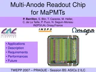
OscillationProject withEmulsion-tRackingApparatus OPERA_ROC : a front-end chip for OPERA multi-anode photomultipliers S. BONDIL1, K. BORER2, A. CAZES1, J.E. CAMPAGNE1, M. HESS2, C. de LA TAILLE1, A. LUCOTTE1,G. MARTIN-CHASSARD1, L. RAUX1, J.P. REPELLIN1 1LAL Orsay IN2P3-CNRS – Université Paris-Sud – B.P. 34 – 91898 Orsay cedex – France 2BERN University Berne- Switzerland http://www.lal.in2p3.fr/opera C. de La Taille IEEE 2003 Portland
Outline • The Opera Target Tracker detector • OPERA_ROC : Readout chip design • Measured performance • Summary, schedule, variants C. de La Taille IEEE 2003 Portland
10 X0 • 2 Targets : • 1.8kT of 206 000 bricks • 2 x 31 walls • Tracker in plastic scintillators -> trigger + brick location + µId 8.3kg ~20 m 8m x 8m 2 Spectrometers: Dipole 1,6T +RPC & Precision Trackers OPERA layout at Gran Sasso • Goal : detection of nm nt oscillation through nt appearance A brick (ECC concept) 56 Pb sheets 1mm 57 Fuji emulsion films +1 Changeable Sheet C. de La Taille IEEE 2003 Portland
7m Target tracker • Scintillator walls for brick location Trigger + Brick Finding etrig > 99 %all channels eBF ~ 70%channel dependant C. de La Taille IEEE 2003 Portland
OPERA_ROC : chip overview • Requirements • Variable gain 1-3 • Auto-trigger on 1/3 photoelectron (p.e.) • Multiplexed charge readout 0.1-100 p.e. • Low noise (< 0.1 p.e.), 1% linearity • Technology: AMS BiCMOS 0.8 m • Chip area : 10 mm2 • Package : QFP100 • 32 channels, 5V power supply • Power consumption : 185 mW C. de La Taille IEEE 2003 Portland
OPERA_ROC : chip architecture • A common variable gain input amplifier • 2 branches : Charge and Time Charge output Trigger output • HISTORY : • chip for HPDs sept 2000 • V1 for MaPMT : spring 2001 • V2 differential 2002 • 3000 chips V3 produced spring 2003 C. de La Taille IEEE 2003 Portland
Variable gain amplifier • Based on scaled current mirrors • 6 bits : 2, 1 , 1/2, 1/4, 1/8, 1/16 • Range : 0 – 3.8 • Linearity ~2% • DC bias = 20 µA • Zin ~ 4 kΩ • Needs a current conveyor upstram Measured gain correction Output waveforms C. de La Taille IEEE 2003 Portland
iout iin Zin =1/gm - > 1/gm(1+A) Phase Zin = 60 Ω Input preamplifier design • Current conveyor • « Super common-base » configuration • Low input impedance : 50 – 100 Ω • Rin = 1/gm1gm2RC=VT2/IC1IC2RC + 50 Ω protection • Can be varied by adjusting IC1 • Low “Inductive term”(50 nH) with careful dimensioning • Large output impedance : ~500 kΩ • Unity current gain Simulated input impedance vs frequency Schematic of preamplifier To mirror Iout Q2 Rc Iin Q1 1 MHz 1 GHz C. de La Taille IEEE 2003 Portland
Slow shaper 0.01 pe Fast shaper Input preamplifier performance ENC vs shaping time • Input impedance, speed and noise Input impedance vs bias current Operating point IC1 = 100 µA Rin=80Ω en = 2.5 nV/√Hz, in = 4 pA/√Hz Preamp output vs gain setting Preamp output vs input capacitance Cd = 0 -> 120 pF, tr 10-90% = 13-23 ns G = 1 -> 3 tr 10-90% = 20-10 ns C. de La Taille IEEE 2003 Portland
0.1p 3p 100k 10k 30k 30k Fast shaper design • Differential configuration • PMOS input pair. Dissipation : 1 mW • Simulated performance • Open loop gain Go=220 : ωc = 300 MHz • Feedback : • Rf = 100 kΩ ; Cf = 100 + 50 fF Simulated output waveforms 0.1-10 p.e. 10 ns 20 ns Simulated open loop gain vs frequency 1 MHz C. de La Taille IEEE 2003 Portland
Gain 1 0.015pe Fast shaper performance Trigger efficiency vs threshold (“s-curves”) • Fast Shaper : • Gain: 2.5 V/pC ( 400 mV/p.e.) • Peaking time: tP ~ 15 ns • Noise RMS: ~ 1.8 mV (~ 0.005 p.e.) • Comparator : • Efficiency: = 100 % down to 1/10 p.e. (goal: 1/3) • Threshold spread: ~ 0.015 pe (pk to pk) • Timewalk : 14.5 ns • Dark rate (no HV) << 1 Hz 0.015pe 50% trigger dispersion 50% trigger vs channel # Gain 3 C. de La Taille IEEE 2003 Portland
Charge readout channel Charge output input Trigger output C. de La Taille IEEE 2003 Portland
Slow shaper design Simulated output waveforms 1-100 p.e. • Differential architecture • NPN centroid input pair. Pd ~ 500 µW • Simulated performance • Open loop gain Go = 720 : ωc = 300MHz • Sallen Key configuration • tp = 160 ns to reduce sensitivity to timing dispersion in scintillator (0.3 % for 10 ns) Simulated open loop gain vs frequency C. de La Taille IEEE 2003 Portland
Charge readout performance • Slow Shaper : • Gain: 125 mV/pC (~ 20 mV/p.e.) • Dispersion : 1?% rms • Peaking time: tP ~ 160 ns ± 2 ns rms • Noise : 1.5 mV rms (0.1 p.e.) • Pedestal spread • ± 6 mV pk-pk ( ± 0.25 p.e.) • 2.5 mV rms Pedestal vs channel number Pedestal dispersion Peaking time uniformity C. de La Taille IEEE 2003 Portland
Charge readout performance (2) • Dynamic range : 100-150 p.e. • ~3 V output swing ; 2.3 V linear range • Linearity : INL ~ 1% • Readout frequency : 5 MHz • 6.4 µs for the 32 channels • Crosstalk < 0.5% C. de La Taille IEEE 2003 Portland
Spectrum with PMT • Measurement of PMT with Bern front-end board • 8 pixels illuminated, trigger set by the chip (at 0.15 p.e.) • « Single » photoelectron injection Single photoelectron readout and spectrum Pedestal : 8.6 mV rms 1.4 mV 1 p.e. -> 20 mV P/V ~ 2 C. de La Taille IEEE 2003 Portland
Summary • OPERA_ROC final for OPERA experiment • Low input impedance variable gain preamp • Autotrigger at 1/10 photoelectron • Multiplexed charge output of 32 channels on 0.1 – 100 p.e. • Schedule • 3400 chips have been produced in july 03 in AMS 0.8 µm BiCMOS • Installation at Gran Sasso scheduled feb 04 – apr 05 • Cost : 67 k€ -> 60c / channel • Several variants • W-Si calorimeter, medical imaging… C. de La Taille IEEE 2003 Portland
1 channel OPA MUX out Gain=10 Amp OPA MUX out Gain=1 Variants ENC vs shaping time • High gain version : PACVG • Charge preamp input • Variable gain : Cf = 0.1 – 3 pF • Low noise : en = 1.3 nV/ @ ID=550µA • ENC = 500 e- + x e-/pF @ tp = 200 ns • Large dynamic range version : FLCPHY3 • W-Si prototype calorimeter for FLC • Low noise, variable feedback charge preamp • Dual gain shaper G1-G10 : dyn. Range = 13 bits • 18 channels, Pd = 10 mW/ch • 1000 chips to be produced end 03 http://www.lal.in2p3.fr/opera C. de La Taille IEEE 2003 Portland
Position 2 N Position 1 Position 3 N x Dosimeter y x tube Variants (2) http://ireswww.in2p3.fr/ires/imaging • Medical imaging (D. Staub et al. IReS Strasbourg) • Dosimeter to avoid overexposure • Lattice of scintillating fibers • MaPMT 64ch Hamamatsu • Photon counting with OPERA_ROC chip C. de La Taille IEEE 2003 Portland