Download
1 / 13
170 likes | 366 Views
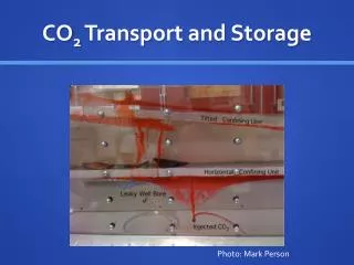
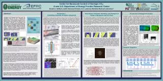
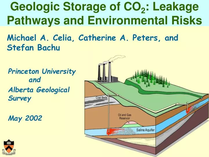
Geologic Storage of CO 2 : Leakage Pathways and Environmental Risks. Princeton University and Alberta Geological Survey May 2002. Michael A. Celia, Catherine A. Peters, and Stefan Bachu. CO 2 Injection and Trapping Mechanisms. Injection Well. Confining Layer(s). ~800 m. Supercritical

E N D
Geologic Storage of CO2: Leakage Pathways and Environmental Risks Princeton University and Alberta Geological Survey May 2002 Michael A. Celia, Catherine A. Peters, andStefan Bachu
CO2 Injection and Trapping Mechanisms Injection Well Confining Layer(s) ~800 m Supercritical CO2 Dissolved CO2 Precipitated Carbonate Minerals Stratigraphic Trapping Solubility Trapping Hydrodynamic Trapping Mineral Trapping
Research Questions How effective are the various trapping mechanisms? What is the likelihood and magnitude of CO2 leakage? What are the environmental impacts of CO2 leakage? Today: Solubility trapping Today: Abandoned wells Today: Mammoth Mtn, and groundwater quality
Simulation of Injection of Supercritical CO2 TOUGH2 Simulator Radial symmetry Isothermal conditions Confining layer permeability of 0.1 mD Target formation porosity 10% and permeability of 100 mD. 790 m Brine 10 m CO2 50 m CO2 injection= 20 kg/s
Simulation of Injection of Supercritical CO2 After 4 years of CO2injection CO2 injection combined with injection of brine above the confining layer Mass of CO2/Volume [kg/m3] Mass of CO2/Volume [kg/m3] Qbrine = 40 kg/s Depth [m] Depth [m] Radial distance [m] Radial distance [m]
Simulation of Injection of CO2Dissolved in Water After 1 year After 50 years Mass of CO2/Volume [kg/m3] Mass of CO2/Volume [kg/m3] Total Mass CO2 injected = 1.2x10⁹ kg Total Mass CO2 injected = 3.1x10⁷ kg seal seal
Leakage Pathways and Trapping Mechanisms Atmosphere SurfaceEcosystems Potable Water fractures,faults, wells Localized vertical migration Confining Layer(s) lateral migration Injected Carbon Dioxide
Simulation of leakage through a single abandoned well Depth [m] • Permeability of a typical well cement ~ 10-17 m2 • Permeability of a medium sand ~ 10-10 m2
Potential Effect on GW Quality drinking-water aquifer groundwater flow 1.2E-07 CO2 leakage 9.0E-08 deep brine aquifer 6.0E-08 concentration, mol/L 3.0E-08 2+ Pb 0.0E+00 10 yr. 8 yr. 6 yr. 4 yr. 2 yr. -50 50 150 250 distance, m
Mammoth Mountain • On the Long Valley Caldera in eastern California • Soil gas surveys revealed CO2 concentrations as high as 95%. (CO2 concentrations > 10% toxic to humans.)
Changes in Metal Uptake in Plants Mn 2001 1989 Ambient soil CO2 Zn Ca Elevated soil CO2 2001 Ca 1989 Mn Zn c b
Acknowledgements • Funding from BP and Ford. • Equations of State: R. Bruant • TOUGH2 Simulations: A. Guswa, S. Gasda • Leakage Estimates: A. Duguid • Groundwater Simulations: P. Jaffe, S. Wang • Mammoth Mountain: S. Myneni, S.J. White