Download
1 / 39
430 likes | 745 Views
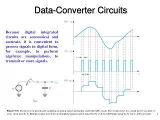
Data Converter Basics. A/D and D/A Conversion. A/D Conversion. D/A Conversion. Quantization. Quantization = division + normalization + truncation Full-scale range (V FS ) is determined by V ref. Quantization Error. N = 3. “Random” quantization error is usually regarded as noise.

E N D
A/D and D/A Conversion A/D Conversion D/A Conversion
Quantization • Quantization = division + normalization + truncation • Full-scale range (VFS) is determined by Vref
Quantization Error N = 3 “Random” quantization error is usually regarded as noise
Quantization Noise Assumptions: • N is large • 0 ≤ Vin≤ VFS and Vin >> Δ • Vinis active • ε is Uniformly distributed • Spectrum of εis white Ref: W. R. Bennett, “Spectra of quantized signals,” Bell Syst. Tech. J., vol. 27, pp. 446-472, July 1948.
Signal-to-Quantization Noise Ratio (SQNR) Assume Vinis sinusoidal with Vp-p = VFS, • SQNR depicts the theoretical performance of an ideal ADC • In reality, ADC performance is limited by many other factors: • Electronic noise (thermal, 1/f, coupling/substrate, etc.) • Distortion (measured by THD, SFDR, IM3, etc.)
FFT Spectrum of Quantized Signal • N = 10 bits • 8192 samples, only f= [0, fs/2] shown • Normalized to Vin • fs = 8192, fin = 779 • finand fs must be incommensurate SQNR = 61.93 dB ENOB = 9.995 bits Ref: W. R. Bennett, “Spectra of quantized signals,” Bell Syst. Tech. J., vol. 27, pp. 446-472, July 1948.
Commensuratefs and fin fs = 8192 fin = 256 fs = 8192 fin = 2048 • Periodic sampling points result in periodic quantization errors • Periodic quantization errors result in harmonic distortion
Spectrum Leakage fs = 8192 fin = 779.3 fs = 8192 fin = 779.3 w/ Blackman window • TD samples must include integer number of cycles of input signal • Windowing can be applied to eliminate spectrum leakage • Trade-off b/t main-lobe width and sideband rejection for different windows
FFT Spectrum with Distortion HD3 HD9 • High-order harmonics are aliased back, visible in [0, fs/2] band • E.g., HD3 @ 779x3+1=2338, HD9 @ 8192-9x779+1=1182
Dynamic Performance • Peak SNDR limited by large-signal distortion of the converter • Dynamic range implies the “theoretical” SNR of the converter
Dynamic Performance Metrics • Signal-to-noise ratio (SNR) • Total harmonic distortion (THD) • Signal-to-noise and distortion ratio (SNDR or SINAD) • Spurious-free dynamic range (SFDR) • Two-tone intermodulation product (IM3) • Aperture uncertainty (related to the frontend S/H and clock) • Dynamic range (DR) – misleading (avoid it if possible!) • Idle channel noise or pattern noise in oversampled converters
Evaluating Dynamic Performance • Signal-to-noise plus distortion ratio (SNDR) • Total harmonic distortion (THD) • Spurious-free dynamic range (SFDR) SNDR = 59.16 dB THD = 63.09 dB SFDR = 64.02 dB ENOB = 9.535 bits HD3 HD9
Static Performance Metrics • Offset (OS) • Gain error (GE) • Monotonicity • Linearity • Differential nonlinearity (DNL) • Integral nonlinearity (INL)
DAC Transfer Characteristic • N = # of bits • VFS = Full-scale input • Δ = VFS/2N = 1LSB • bi = 0 or 1 • Multiplication Note: Vout (bi = 1, for all i) = VFS - Δ = VFS(1-2-N) ≠ VFS
Offset Vos
Differential and Integral Nonlinearities DNL < -1 ? • DNL = deviation of an output step from 1 LSB (= Δ = VFS/2N) • INL = deviation of the output from the ideal transfer curve
DNL and INL INL = cumulative sum of DNL
DNL and INL Smooth Noisy • DNL measures the uniformity of quantization steps, or incremental (local) nonlinearity; small input signals are sensitive to DNL. • INL measures the overall, or cumulative (global) nonlinearity; large input signals are often sensitive to both INL (HD) and DNL (QE).
Measure DNL and INL (Method I) Endpoint stretch Endpoints of the transfer characteristic are always at 0 and VFS-Δ
Measure DNL and INL (Method II) Least-square fit and stretch (“detrend”) Endpoints of the transfer characteristic may not be at 0 and VFS-Δ
Measure DNL and INL Method I (endpoint stretch) Σ(INL) ≠ 0 Method II (LS fit & stretch) Σ(INL) = 0
Ideal ADC Transfer Characteristic Note the systematic offset! (floor, ceiling, and round)
DNL and Missing Code • DNL = ? • Can DNL < -1? DNL = deviation of an input step width from 1 LSB (= VFS/2N = Δ)
DNL and Nonmonotonicity • DNL = ? • How can we even measure this? DNL = deviation of an input step width from 1 LSB (= VFS/2N = Δ)
INL • Any code • Missing? • Nonmonotonic? INL = deviation of the step midpoint from the ideal step midpoint (method I and II …)
10-bit ADC Example • 1024 codes • No missing code! • Plotted against the digital code, not Vin • Code density test (CDT) DNL must always be greater or equal to -1 LSB!
Code Density Test Ball casting problem: # of balls collected by each bin (ni) is proportional to the bin size (converter step size)
CDT and Nonmonotonicity • Two transition steps for one code?! How to plot INL/DNL? • CDT can be misleading in determining the static nonlinearity
Nyquist-Rate ADC • Digitizes input signal up to Nyquist frequency (fN=fs/2) • Minimum sample rate (fs) for a given input bandwidth • Each sample is digitized to the maximum resolution of converter • Often referred to as the “black box” version of digitization
Nyquist-Rate ADC (N-Bit, Binary) • Word-at-a-time (1 step)† ← fast • Flash • Level-at-a-time (2N steps) ← slowest • Integrating (Serial) • Bit-at-a-time (N steps) ← slow • Successive approximation • Algorithmic (Cyclic) • Partial word-at-a-time (1 < M ≤ N steps) ← medium • Subranging • Pipeline • Others (1 ≤ M ≤ N step) • Folding ← relatively fast • Interleaving (of flash, pipeline, or SA) ← fastest † the number in the parentheses is the “latency” of conversion, not “throughput”
Building Blocks for Data Converters • Sample-and-Hold (Track-and-Hold) Amplifier • Switched-Capacitor Amplifiers, Integrators, and Filters • Operational Amplifier • Comparators (Preamplifier and Latch) • Voltage and Current DAC’s • Current Sources • Voltage/Current/Bandgap References