Download
1 / 42
430 likes | 561 Views
Introduction to Computer Architecture and System. 353156 – Microprocessor Asst. Prof. Dr. Choopan Rattanapoka and Asst. Prof. Dr. Suphot Chunwiphat. Objective. To understand What is the computer Von Neumann Architecture What is the microprocessors MU0 – Processor Instruction cycle

E N D
Introduction to Computer Architecture and System 353156 – Microprocessor Asst. Prof. Dr. ChoopanRattanapoka and Asst. Prof. Dr. SuphotChunwiphat
Objective • To understand • What is the computer • Von Neumann Architecture • What is the microprocessors • MU0 – Processor • Instruction cycle • Mnemonic and Machine Code
What is the Computer • A computer is a programmable machine designed to sequentially and automatically carry out a sequence of arithmetic or logical operations. The particular sequence of operations can be changed readily, allowing the computer to solve more than one kind of problem. • The basic functions of the computer are : • Inputting data • Outputting data • Processing data • Storing data
Computer Technology Disk size increases 2x every year Processor speed increases 2x every 18 months
Unit of Measurement in Computer System • Normally, we use International System of Units (SI : Système international d'unités) as unit of measurement. But in computer system, we use binary prefix. For Example : A 400GB harddisk Manufacturer uses GB in SI unit, so the harddisk has 400,000,000,000 B capacity In MS Windows, it use GB as 230 , so the Windows can see the harddisk around 372 GB
Von Neumann Architecture • The earliest computing machines had fixed programs. Changing the program of a fixed-program machine requires re-wiring, re-structuring, or re-designing the machine. • The idea of the stored-program computer changed all that: a computer that by design includes an instruction set and can store in memory a set of instructions (a program) that details the computation. • Characteristics of von Neumann machine • Both data and instructions are stored in a read/write memory. • Memory contents are addressable by location without regard for the type of data contained there • Execution occurs in a sequential fashion by reading consecutive instructions from memory John Von Neumann 1948 : You insist that there is something a machine cannot do. If you will tell me precisely what it is that a machine cannot do, then I can always make a machine which will do just that!
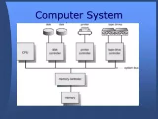
Main Components of a Computer Main Memory Microprocessor System bus Instruction Instruction Instruction I/O Module Data Data Data buffer
What is the Microprocessor? • Microprocessor is a very large-scale integrated circuit (VLSI) that uses the architecture of the general-purpose digital computer. • Microprocessors are based on the von Neumann model of a stored program computer • The stored program computer, a microprocessor’s program is stored in memory along with its data
MPU, MCU, CPU • Microprocessor Units (MPU) tend to be aimed at computer applications; they tend to have minimal "extras" on-chip. • Intel Pentium • AMD opteron • Microcontroller Units (MCU) tend to be aimed at embedded control applications; they tend to consist of a processor plus a number of useful peripherals (internal I/O modules, memory, etc). • 8051 • PIC • ARM • Central Processing Unit (CPU) could refer to • the actual processor part of a microcontroller. • the microprocessor within a computer.
Where are the CPU ? Supercomputer Personal computer Mobile phone High computing speed Low computing speed Embedded Devices High power consumption Low power consumption Size : big Size : small
Central Processing Unit (CPU) • Central Processing Unit (CPU) contains : • ALU (Arithmetic Logic Unit) • The ALU performs computational functions such as Add, Subtract, AND, OR, Compare, Increment, and Decrement. • Control Logic • The control logic decodes and executes the program. It also controls the memory, input, and output operation of the microprocessor • Registers : • The registers (fast memory, local to CPU) use to store temporary data and instructions
Memory • The communication between microprocessor and memory has 3 types of signals (buses). • Address bus – determines the location of memory • Data bus – carries the contents of the location • Control bus – governs the information transfer • The width of the address bus determines the size of memory. (how many location) • The width of the data bus determines the size of content. (how many bits can each location store) Control bus Memory R/W Enable Address bus A11:0 Data bus D15:0
Memory, Registers, and ALU CPU Memory ALU Registers Address bus A11:0 Data bus D15:0 Address bus A11:0 Data bus D15:0 Control bus Control bus
MU0 – A Very Simple Processor • MU0 processor is an abstract design for teaching purposes at University of Manchester. • MU0 is a simple processor with 16-bits instruction and minimal hardware. address bus • Program Counter (PC) • Holds address of the next instruction to execute • Accumulator (ACC) • Holds data being processed • Arithmetic Logic Unit (ALU) • Performs operations on data • Instruction Register (IR) • Holds current instruction code being executed control Memory PC IR ALU ACC data bus
Instructions • Instruction usually has 2 parts • Opcode determines what is to be done • Operand specifies where/what is the data Opcode Operand 1 word
The Instruction Cycle • An instruction cycle is the basic operation cycle of a computer, sometimes called • fetch-and-execute cycle • fetch-decode-execute cycle • FDX • Each computer's CPU can have different cycles based on different instruction sets, but will be similar to the following cycle: • Fetch instruction – Supply instruction address and read an instruction from memory on the data bus. • Decode instruction – Stored instruction is interpreted by CPU • Fetch Operand – Supply address of data and read data into CPU • Execution instruction - Perform the necessary action by CPU
Step 1: Fetch Instruction (1) address bus • CPU outputs value of program counter on address bus • Memory puts contents at the instruction address on the data bus • Instruction is stored in instruction register control Memory IR PC IR ALU ACC data bus
Step 1: Fetch Instruction (2) address bus • Program counter value is pushed onto the address bus • The ALU increment this value by k and put it back into Program counter control Memory PC PC PC = PC + k IR ALU ACC data bus
Step 2: Decode Instruction address bus • The instruction word stored in IR is decoded by internal logic to provide control signals to ALU and other internal circuits inside CPU control Memory IR PC IR ALU ACC data bus
Step 3: Fetch Operand address bus • The instruction register provides the address of the data to be processed • Memory supplies the operand data on the data bus to the CPU, ready for processing either by the ALU or the ACC control Memory PC IR IR ALU ACC data bus
Step 4: Execution Instruction address bus • Processing is performed on the operand by the ALU according to the instruction • The result is put back into the Accumulator (ACC) control Memory PC IR ALU ACC ACC data bus
MU0 – Instructions • Let us assume that the processor only has 8 instructions and can only access a maximum of 4k byte of memory. This implies that the address bus is only 12-bits wide • MU0 is a 16-bit microprocessor, Thus ALL instructions are 16-bits wide. • The 16-bit instruction code (machine code) has a format : • Top 4 bits define the operation code (opcode). • Next 12 bits define the memory address of the operand data. 12 bits 4 bits Opcode Operand
MU0 – Instruction Set • 2 load/store instructions: LDA, STO • 2 computation instructions: ADD, SUB • 4 control flow instructions: JMP, JGE, JNE, STP
Example : First Program (1) • The simplest use of our microprocessor • Add two numbers • Let’s assume these numbers are stored at two consecutive locations in memory, with addresses 2E and 30 • Let’s assume we wish to store the result back to memory address 32 • Hint : we need to load accumulator with 1 value, add the other, and then store the result back into memory
Example : First Program (2) • Load accumulator with 1 value • LDA 2E • Add the other • ADD 30 • Store the result back into memory • STO 32 • Stop program • STP
Example : How program works MU0 000 002E Address bus 2030 002 004 1032 PC 000 7000 006 ALU . . . ACC Data bus 00AA 02E Control IR 030 0012 032 . . .
Example : Fetch-Decode Instruction MU0 000 002E Address bus 2030 002 004 1032 PC 000 7000 006 ALU . . . ACC Data bus 00AA 02E IR 002E Control IR 030 0012 032 . . .
Example : Fetch-Decode Instruction MU0 000 002E Address bus 2030 002 004 1032 PC 002 PC 000 7000 006 ALU ALU . . . ACC Data bus 00AA 02E Control IR 002E 030 0012 032 . . .
Example : Fetch Operand MU0 000 002E Address bus 2030 002 004 1032 PC 002 7000 006 ALU . . . ACC 00AA ACC Data bus 00AA 02E Control IR 002E 030 0012 032 . . .
Example : Execution Instruction MU0 000 002E Address bus 2030 002 004 1032 PC 002 7000 006 ALU . . . ACC 00AA Data bus 00AA 02E Control IR 002E 030 0012 032 . . .
Example : Fetch-Decode Instruction MU0 000 002E Address bus 2030 002 004 1030 PC 002 7000 006 ALU . . . ACC 00AA Data bus 00AA 02E Control IR 2030 IR 002E 030 0012 032 . . .
Example : Fetch-Decode Instruction MU0 000 002E Address bus 2030 002 004 1032 PC 002 PC 004 7000 006 ALU ALU . . . ACC 00AA Data bus 00AA 02E Control IR 2030 030 0012 032 . . .
Example : Fetch Operand MU0 000 002E Address bus 2030 002 004 1032 PC 004 7000 006 ALU ALU 0012 . . . ACC 00AA Data bus 00AA 02E Control IR 2030 030 0012 032 . . .
Example : Execution Instruction MU0 000 002E Address bus 2030 002 004 1032 PC 004 7000 006 ALU 0012 ALU 0012 + 00AA . . . ACC 00BC ACC 00AA Data bus 00AA 02E Control IR 2030 030 0012 032 . . .
Example : Fetch-Decode Instruction MU0 000 002E Address bus 2030 002 004 1032 PC 004 7000 006 ALU . . . ACC 00BC Data bus 00AA 02E Control IR 1032 IR 2030 030 0012 032 . . .
Example : Fetch-Decode Instruction MU0 000 002E Address bus 2030 002 004 1032 PC 004 PC 006 7000 006 ALU ALU . . . ACC 00BC Data bus 00AA 02E Control IR 1032 030 0012 032 . . .
Example : Execute Instruction MU0 000 002E Address bus 2030 002 004 1032 PC 006 7000 006 ALU . . . ACC 00BC Data bus 00AA 02E Control IR 1032 030 0012 032 00BC . . .
Example : Fetch-Decode Instruction MU0 000 002E Address bus 2030 002 004 1032 PC 006 7000 006 ALU . . . ACC 00BC Data bus 00AA 02E Control IR 7000 IR 1032 030 0012 032 00BC . . .
Example : Fetch-Decode Instruction MU0 000 002E Address bus 2030 002 004 1032 PC 006 PC 008 7000 006 ALU ALU . . . ACC 00BC Data bus 00AA 02E Control IR 7000 030 0012 032 00BC . . .
Example : Execute Instruction MU0 000 002E Address bus 2030 002 004 1032 PC 008 7000 006 ALU . . . ACC 00BC Data bus 00AA 02E Control IR 7000 030 0012 032 00BC . . . END
Assignment 2 1. Write a program in mnemonic code for processor MU0 to calculate A + B + C - D where the value of • A stores at address 2E0 • B stored at address 2E2 • C stored at address 2E4 • D stored at address 2E6 The result will be store at address 2F0 2. Write the machine code for processor MU0 from the mnemonic code in question 1