Download
1 / 53
540 likes | 685 Views
Chapter 2: Review of Important Networking Concepts. Magda El Zarki Dept. of CS UC Irvine elzarki@uci.edu http://www.ics.uci.edu/~magda. The Internet: A Collection of Networks. The Internet: A Mesh of Links. millions of connected computing devices: hosts = end systems

E N D
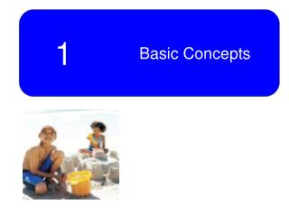
Chapter 2: Review of Important Networking Concepts Magda El Zarki Dept. of CS UC Irvine elzarki@uci.edu http://www.ics.uci.edu/~magda
millions of connected computing devices: hosts = end systems running network apps PC Mobile network server Global ISP wireless laptop cellular handheld Home network Regional ISP access points wired links Institutional network router What’s the Internet: “nuts and bolts”view • communication links • fiber, copper, radio, satellite • transmission rate = bandwidth • routers: forward packets (chunks of data)
communication infrastructure enables distributed applications: Web, VoIP, email, games, e-commerce, file sharing communication services provided to apps: reliable data delivery from source to destination “best effort” (unreliable) data delivery What’s the Internet: a service view
mesh of interconnected routers the fundamental question: how is data transferred through net? circuit switching: dedicated circuit per call: telephone net packet-switching: data sent thru net in discrete “chunks” The Network Core
End-end resources reserved for “call” link bandwidth, switch capacity dedicated resources: no sharing circuit-like (guaranteed) performance call setup required Network Core: Circuit Switching
network resources (e.g., bandwidth) divided into “pieces” dividing link bandwidth into “pieces” frequency division time division pieces allocated to calls resource piece idle if not used by owning call (no sharing) Network Core: Circuit Switching
Example: 4 users FDM frequency time TDM frequency time Circuit Switching: FDM and TDM
each end-end data stream divided into packets user A, B packets share network resources each packet uses full link bandwidth resources used as needed Network Core: Packet Switching
Sequence of A & B packets does not have fixed pattern, bandwidth shared on demand statistical multiplexing. TDM: each host gets same slot in revolving TDM frame. D E Packet Switching: Statistical Multiplexing 100 Mb/s Ethernet C A statistical multiplexing 1.5 Mb/s B queue of packets waiting for output link
Networking Concepts • Protocol Architecture • Protocol Layers • Encapsulation • IP Addressing
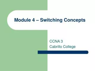
DNS: What is the IP address of “neon.tcpip-lab.edu”? DNS: The IP address of “neon.tcpip-lab.edu” is 128.143.71.21 ARP: What is the MAC address of 128.143.137.1? ARP: What is the MAC address of 128.143.71.21? ARP: The MAC address of 128.143.137.1 is 00:20:af:03:98:28 ARP: The MAC address of 128.143.137.1 is 00:e0:f9:23:a8:20 128.143.71.21 is not on my local network. Therefore, I need to send the packet to my default gateway with address 128.143.137.1 Sending a packet from Argon to Neon 128.143.71.21 is on my local network. Therefore, I can send the packet directly. frame frame
Sequence of events: 1.Web client at Argon starts an HTTP Request. 2.Argon contacts its DNS server to translate the domain name “neon.cerf.edu” into IP address “128.143.71.21” and looks up the well-known port number of the web server (port 80). 3.The HTTP client at Argon requests a TCP connection to port 80 at IP address 128.143.71.21. 4.The TCP client at Argon requests its Internet Protocol (IP) to deliver an IP datagram with the connection request to destination 128.143.71.21. 5.The IP process at Argon decides that it cannot deliver the IP datagram directly, and decides to send the IP datagram to its default gateway 128.143.137.1. 6.The Address Resolution Protocol (ARP) at Argon sends an ARP request for the MAC address of IP address 128.143.137.1. 7.The ARP request is broadcast by the Ethernet device driver at Argon to all devices on the Ethernet network. 8.The router with IP address 128.143.137.1 responds with an ARP Response to Argon which includes MAC address 00:e0:f9:23:a8:20. 9.The IP process at Argon asks its Ethernet device driver to send the IP datagram in an Ethernet frame to MAC address 00:e0:f9:23:a8:20. 10.Ethernet device driver at router with MAC address 00:e0:f9:23:a8:20 unpacks the IP datagram, and passes it to its IP process. 11.The IP process at the router decides that it can deliver the IP datagram with destination 128.143.137.21 directly (without the need of additional routers). 12.The Address Resolution Protocol (ARP) at the router sends an ARP request for the MAC address of IP address 128.143.137.21. 13.The ARP request is broadcast by the Ethernet device driver at the router to all devices on the Ethernet network. 14.Neon (which has IP address 128.143.137.21) responds with an ARP Response to the router which includes MAC address 00:20:af:03:98:28. 15.The IP process at the router asks its Ethernet device driver to send the IP datagram in an Ethernet frame to MAC address 00:20:af:03:98:28. 16.The Ethernet device driver at Neon unpacks the IP datagram contained in the Ethernet frame, and passes it to its IP process. 17.The IP process unpacks the TCP connection request contained in the IP datagram and passes it to the TCP server at port 80. 18.The TCP server at port 80 processes the TCP connection request.
Communications Architecture • The complexity of the communication task is reduced by using multiple protocol layers: • Each protocol is implemented independently • Each protocol is responsible for a specific subtask • Protocols are grouped in a hierarchy • A structured set of protocols is called a communicationsarchitectureorprotocol suite
The TCP/IP protocol suite is the protocol architecture of the Internet The TCP/IP suite has four layers: Application, Transport, Network, and Data Link Layer End systems (hosts) implement all four layers. Gateways (Routers) only have the bottom two layers. TCP/IP Protocol Suite
Functions of the Layers • Data Link Layer: • Service: Reliable transfer of frames over a link Media Access Control on a LAN • Functions: Framing, media access control, error checking • Network Layer: • Service: Move packets from source host to destination host • Functions: Routing, addressing • Transport Layer: • Service: Delivery of data between hosts • Functions: Connection establishment/termination, error control, flow control • Application Layer: • Service: Application specific (delivery of email, retrieval of HTML documents, reliable transfer of file) • Functions: Application specific
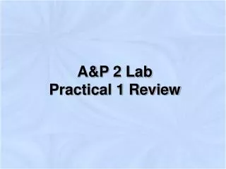
TCP/IP Suite and OSI Reference Model The TCP/IP protocol stack does not define the lower layers of a complete protocol stack
Send IP data-gram to 128.143.71.21 Frame is an IP datagram Frame is an IP datagram IP datagram is a TCP segment for port 80 Send HTTP Request to neon Establish a connection to 128.143.71.21 at port 80 Open TCP connection to 128.143.71.21 port 80 Send IP datagram to 128.143.71.21 Send a datagram (which contains a connection request) to 128.143.71.21 Send the datagram to 128.143.137.1 Send the datagram to 128.143.7.21 Send Ethernet frame to 00:e0:f9:23:a8:20 Send Ethernet frame to 00:20:af:03:98:28 Layers in the Example
Layers and Services • Service provided by TCP to HTTP: • reliable transmission of data over a logical connection • Service provided by IP to TCP: • unreliable transmission of IP datagrams across an IP network • Service provided by Ethernet to IP: • transmission of a frame across an Ethernet segment • Other services: • DNS: translation between domain names and IP addresses • ARP: Translation between IP addresses and MAC addresses
Encapsulation and Demultiplexing • As data is moving down the protocol stack, each protocol is adding layer-specific control information
Encapsulation and Demultiplexing in our Example • Let us look in detail at the Ethernet frame between Argon and the Router, which contains the TCP connection request to Neon. • This is the frame in hexadecimal notation. 00e0 f923 a820 00a0 2471 e444 0800 4500 002c 9d08 4000 8006 8bff 808f 8990808f 4715 065b 0050 0009 465b 0000 0000 6002 2000 598e 0000 0204 05b4
Encapsulation and Demultiplexing: TCP Header Option: maximum segment size
No Application Data in this frame Encapsulation and Demultiplexing: Application data
Different Views of Networking • Different Layers of the protocol stack have a different view of the network. This is HTTP’s and TCP’s view of the network.
Network View of Ethernet • Ethernet’s view of the network
IP Addresses • Structure of an IP address • Subnetting • Classless Inter Domain Routing (CIDR)
What is an IP Address? • An IP address is a unique global address for a network interface. • Each device on the Internet has a network interface. Some devices may have more than one! Example: ??? • Each device belongs to a domain. A • An IP address: • is a 32 bit long identifier • encodes a network number (network prefix) and a host number
Dotted Decimal Notation • IP addresses are written in a so-called dotted decimal notation • Each byte is identified by a decimal number in the range [0..255]: 10000000 10001111 10001001 10010000 1st Byte = 128 2nd Byte = 143 3rd Byte = 137 4th Byte = 144 128.143.137.144
Network prefix and Host number • The network prefix identifies a network and the host number identifies a specific host (actually, interface on the network). • How do we know how long the network prefix is? • The network prefix is implicitly defined (class-based addressing) • The network prefix is indicated by a netmask. network prefix host number
Example • Example: ellington.cs.virginia.edu • Network id is: 128.143.0.0 • Host number is: 137.144 • Network mask is: 255.255.0.0 or ffff0000 • Prefix notation: 128.143.137.144/16 • Network prefix is 16 bits long 128.143 137.144
Subnetting • Since the networks of some organizations grow large, network operators can decide to subdivide the network into smaller subnetworks and assign each subnetwork its own network address. • This process is known as subnetting. • Subnettingis done by allocating some of the leading bits of the host number to indicate a subnet number. • With subnetting, the network prefix and the subnet number make up an extended network prefix. • The extended prefix can be expressed in terms of a subnetmask or, using CIDR notation, by adding the length of the extended subnetmask after the IP address. • For example, for Argon, the first byte of the host number (the third byte of the IP address) is used to denote the subnet number. • 128.143.0.0/16 is the IP address of the network, • 128.143.137.0/24 is the IP address of the subnet, • 128.143.137.144/32is the IP address of the host, and • 255.255.255.0is the subnetmask of the host
Basic Idea of Subnetting • Split the host number portion of an IP address into a subnet number and a (smaller) host number. • Result is a 3-layer hierarchy • Then: • Subnets can be freely assigned within the organization • Internally, subnets are treated as separate networks • Subnet structure is not visible outside the organization network prefix host number network prefix subnet number host number extended network prefix
Typical Addressing Plan for an Organization that uses subnetting • Each layer-2 network (Ethernet segment, FDDI segment) is allocated a subnet address when connected to a router. R 128.143.0.0/16 Gateway Router R R
Advantages of Subnetting • With subnetting, IP addresses use a 3-layer hierarchy: • Network • Subnet • Host • Improves efficiency of IP addresses by not consuming an entire address space for each physical network. • Reduces router complexity. Since external routers do not know about subnetting, the complexity of routing tables at external routers is reduced. • Note: Length of the subnet mask need not be identical for all subnetworks.
CIDR - Classless Inter Domain Routing • Goals: • Restructure IP address assignments to increase efficiency • Hierarchical routing aggregation to minimize route table entries Key Concept:The length of the network id (prefix) in the IP addresses is kept arbitrary • Consequence: Routers advertise the IP address and the length of the prefix
CIDR Example • CIDR notation of a network address: 192.0.2.0/18 • "18" says that the first 18 bits are the network part of the address (and 14 bits are available for specific host addresses) • The network part is called the prefix