Download
1 / 1
10 likes | 133 Views
TR4. TC5. TL3. BR2. BC6. BL1. TL3. CFEB Input Cable Labeling Scheme. CFEB End. Pin One. 3. Red Stripe. Straight Ground Lug. Label (on CFEB End Only). 4. CFEB Input Cable Assembly Order Start with layer 1 and work down to layer 6 in order.

E N D
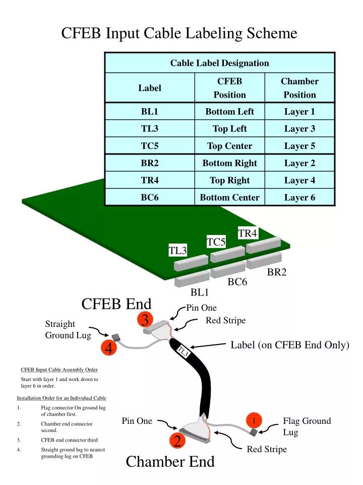
TR4 TC5 TL3 BR2 BC6 BL1 TL3 CFEB Input Cable Labeling Scheme CFEB End Pin One 3 Red Stripe Straight Ground Lug Label (on CFEB End Only) 4 CFEB Input Cable Assembly Order Start with layer 1 and work down to layer 6 in order. • Installation Order for an Individual Cable • Flag connector On ground lug of chamber first. • Chamber end connector second. • CFEB end connector third • Straight ground lug to nearest grounding lug on CFEB Pin One 1 Flag Ground Lug 2 Red Stripe Chamber End