Download
1 / 18
210 likes | 417 Views
Chapter 5 Fundamental Concepts in Video. 5.1 Types of Video Signals. Component video • Component video : Higher-end video systems make use of three separate video signals for the red, green, and blue image planes . Each color channel is sent as a separate video signal .

E N D
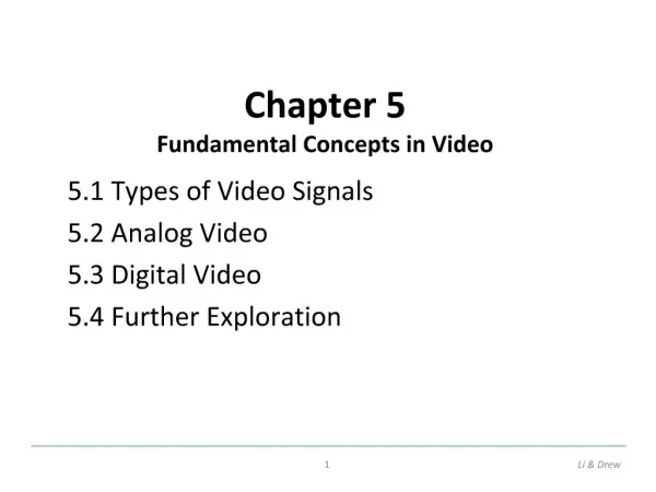
Chapter 5Fundamental Concepts in Video Li & Drew
5.1 Types of Video Signals • Component video • • Component video: Higher-end video systems make use of three separate video signals for the red, green, and blue image planes. Each color channel is sent as a separate video signal. • (a) Most computer systems use Component Video, with separatesignals for R, G, and B signals. • (b) For any color separation scheme, Component Video gives the best color reproduction since there is no “crosstalk” between the three channels. • (c) This is not the case for S-Video or Composite Video, discussed next. Component video, however, requires more bandwidth and good synchronization of the three components. Li & Drew
Composite Video — 1 Signal • • Composite video: color (“chrominance”) and intensity (“luminance”) signals are mixed into a single carrier wave. • a) Chrominance is a composition of two color components (I and Q, or U and V). • b) In NTSC TV, e.g., I and Q are combined into a chroma signal, and a color subcarrier is then employed to put the chroma signal at the high-frequency end of the signal shared with the luminance signal. • c) The chrominance and luminance components can be separated at the receiver end and then the two color components can be further recovered. • d) When connecting to TVs or VCRs, Composite Video uses only one wire and video color signals are mixed, not sent separately. The audio and sync signals are additions to this one signal. • • Since color and intensity are wrapped into the same signal, some interference between the luminance and chrominance signals is inevitable. Li & Drew
S-Video — 2 Signals • • S-Video: as a compromise, (separated video, or Super-video, e.g., in S-VHS) uses two wires, one for luminance and another for a composite chrominance signal. • • As a result, there is less crosstalk between the color information and the crucial gray-scale information. • • The reason for placing luminance into its own part of the signal is that black-and-white information is most crucial for visual perception. • – In fact, humans are able to differentiate spatial resolution in grayscaleimages with a much higher acuity than for the color part of color images. • – As a result, we can send less accurate color information than must be sent for intensity information — we can only see fairly large blobs of color, so it makes sense to send less color detail. Li & Drew
5.2 Analog Video • • An analog signal f(t) samples a time-varying image. So-called “progressive” scanning traces through a complete picture (a frame) row-wise for each time interval. • • In TV, and in some monitors and multimedia standards as well, another system, called “interlaced” scanning is used: • a) The odd-numbered lines are traced first, and then the even-numbered • lines are traced. This results in “odd” and “even” fields — two fields • make up one frame. • b) In fact, the odd lines (starting from 1) end up at the middle of a line • at the end of the odd field, and the even scan starts at a half-way point. Li & Drew
Fig. 5.1: Interlaced raster scan • c) Figure 5.1 shows the scheme used. First the solid (odd) lines are traced, P to Q, then R to S, etc., ending at T; then the even field starts at U and ends at V. • d) The jump from Q to R, etc. in Figure 5.1 is called the horizontal retrace, during which the electronic beam in the CRT is blanked. The jump from T to U or V to P is called the vertical retrace. Li & Drew
• Because of interlacing, the odd and even lines are displaced in time from each other — generally not noticeable except when very fast action is taking place on screen, when blurring may occur. • • For example, in the video in Fig. 5.2, the moving helicopter is blurred more than is the still background. Li & Drew
Fig. 5.2: Interlaced scan produces two fields for each frame. (a) The • video frame, (b) Field 1, (c) Field 2, (d) Difference of Fields (a) (b) (c) (d) Li & Drew
NTSC Video • • NTSC (National Television System Committee) TV standardis mostly used in North America and Japan. It uses the familiar 4:3 aspect ratio (i.e., the ratio of picture width to its height) and uses 525 scan lines per frame at 30 frames per second (fps). • a) NTSC follows the interlaced scanning system, and each frame is divided into two fields, with 262.5 lines/field. b) Vertical retrace takes place during 20 lines reserved for control information at the beginning of each field. c) Similarly, almost 1/6 of the raster at the left side is blanked for horizontal retrace and sync. The non-blanking pixels are called active pixels. d) It is known that pixels often fall in-between the scan lines. Therefore, even with non-interlaced scan, NTSC TV is only capable of showing about 70% of the active lines. With interlaced scan, this could be as low as 50%. Li & Drew
PAL Video • • PAL (Phase Alternating Line) is a TV standard widely used in Western Europe, China, India, and many other parts of the world. • • PAL uses 625 scan lines per frame, at 25 frames/second, with a 4:3 aspect ratio and interlaced fields. • (a) PAL uses the YUV color model. It uses an 8 MHz channel and allocates a bandwidth of 5.5 MHz to Y, and 1.8 MHz each to U and V. The color subcarrier frequency isfsc≈ 4.43 MHz. • (b) In order to improve picture quality, chroma signals have alternate signs (e.g., +U and -U) in successive scan lines, hence the name “Phase Alternating Line”. • (c) This facilitates the use of a (line rate) comb filter at the receiver — the signals in consecutive lines are averaged so as to cancel the chroma signals (that always carry opposite signs) for separating Y and C and obtaining high quality Y signals. Li & Drew
SECAM Video • • SECAM stands for Système Electronique Couleur Avec Mémoire, the third major broadcast TV standard. • • SECAM also uses 625 scan lines per frame, at 25 frames per second, with a 4:3 aspect ratio and interlaced fields. • • SECAM and PAL are very similar. They differ slightly in their color coding scheme: • (a) In SECAM, U and V signals are modulated using separate color subcarriers at 4.25 MHz and 4.41 MHz respectively. • (b) They are sent in alternate lines, i.e., only one of the U or V signals will be sent on each scan line. Li & Drew
• Table 5.2 gives a comparison of the three major analog broadcast TV systems. • Table 5.2: Comparison of Analog Broadcast TV Systems Li & Drew
5.3 Digital Video • • The advantages of digital representation for video are many. For example: • (a) Video can be stored on digital devices or in memory, ready to be processed (noise removal, cut and paste, etc.), and integrated to various multimedia applications; • (b) Direct access is possible, which makes nonlinear video editing achievable as a simple, rather than a complex, task; • (c) Repeated recording does not degrade image quality; • (d) Ease of encryption and better tolerance to channel noise. Li & Drew
Chroma Subsampling • • Since humans see color with much less spatial resolution than they see black and white, it makes sense to “decimate” the chrominance signal. • • Interesting (but not necessarily informative!) names have arisen to label the different schemes used. • • To begin with, numbers are given stating how many pixel values, per four original pixels, are actually sent: • (a) The chromasubsampling scheme “4:4:4” indicates that no chromasubsampling is used: each pixel’s Y, Cb and Cr values are transmitted, 4 for each of Y, Cb, Cr. Li & Drew
(b) The scheme “4:2:2” indicates horizontal subsampling of the Cb, Cr signals by a factor of 2. That is, of four pixels horizontally labelled as 0 to 3, all four Ys are sent, and every two Cb’s and two Cr’s are sent, as (Cb0, Y0)(Cr0, Y1)(Cb2, Y2)(Cr2, Y3)(Cb4, Y4), and so on (or averaging is used). • (c) The scheme “4:1:1” subsamples horizontally by a factor of 4. • (d) The scheme “4:2:0” subsamples in both the horizontal and vertical dimensions by a factor of 2. Theoretically, an average chroma pixel is positioned between the rows and columns as shown Fig.5.6. • • Scheme 4:2:0 along with other schemes is commonly used in JPEG and MPEG (see later chapters in Part 2). Li & Drew
Fig. 5.6: Chromasubsampling Li & Drew
HDTV (High Definition TV) • • The main thrust of HDTV (High Definition TV) is not to increase the “definition” in each unit area, but rather to increase the visual field especially in its width. • • For video, MPEG-2 is chosen as the compression standard. For audio, AC-3 is the standard. It supports the so-called 5.1 channel Dolby surround sound, i.e., five surround channels plus a subwoofer channel. • • The salient difference between conventional TV and HDTV: • (a) HDTV has a much wider aspect ratio of 16:9 instead of 4:3. • (b) HDTV moves toward progressive (non-interlaced) scan. The rationale is that interlacing introduces serrated edges to moving objects and flickers along horizontal edges. Li & Drew
• It is planned to replace all analog broadcast services with digital TV broadcasting by the year 2009. The services provided will include: • – SDTV (Standard Definition TV): the current NTSC TV or higher. • – EDTV (Enhanced Definition TV): 480 active lines or higher, i.e., the third and fourth rows in Table 5.4. • – HDTV (High Definition TV): 720 active lines or higher. Li & Drew