Download
1 / 24
240 likes | 330 Views
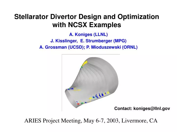
Stellarator Divertor Design and Optimization with NCSX Examples. A. Koniges (LLNL) J. Kisslinger, E. Strumberger (MPG) A. Grossman (UCSD); P. Mioduszewski (ORNL). Contact: koniges@llnl.gov. ARIES Project Meeting, May 6-7, 2003, Livermore, CA. General Goals.

E N D
Stellarator Divertor Design and Optimization with NCSX Examples A. Koniges (LLNL) J. Kisslinger, E. Strumberger (MPG) A. Grossman (UCSD); P. Mioduszewski (ORNL) Contact: koniges@llnl.gov ARIES Project Meeting, May 6-7, 2003, Livermore, CA
General Goals • Develop the divertor/limiter concept for NCSX via: • Moderate/uniformly distributed power/particle load at the divertor • Desirable Qualities: • Small angles of incidence • Adequate coverage by plates • Large areas of incidence within plate area • Li383 Results: • Footprints and inclinations of field line intersections with limiting surfaces for candidate NCSX Plasma (li383) • Diffused field-line lengths (related to connection length) • Heat flux estimates • Final Design Optimization: • Final coil set, Vary b, more accurate field outside LCMS • Iterate and optimize positions of actual divertor/limiter plates • Could extend to alphas -- key is accurate diffusion
Methodology • Start with Finite- reference configuration from VMEC/MFBE solution inside and outside LCMS • (could be replaced by PIES solution eventually) • Divertor, Limiter and/or first-wall-like surface(s) specified • Fast-method to • Trace field lines using diffusion to mitigate spurious points • Simulate anomalous plasma transport via diffusive effects • Calculate intersection locations with limiting surfaces • Calculate inclination angle of intersection • Estimates of field-line length Not just field-line tracing!
VMEC LCMS Outer Limiting Surface Magnetic field inside and outside LCMS is obtained from VMEC/MFBE Solution (Li383)
People often start field line tracing marching outward from some location Surfaces and intersections calculated without this method can show spurious points
-Obtain a starting surface by integrating just inside the VMEC LCMS. -Field line tracing with diffusion started from this surface. -When a field line terminates from an intersection, a new starting point is calculated by linear interpolation.
Diffusive effects model anomalous transport and assure field line space is covered • Cross-field diffusion is assumed anomalous and of order 104 cm2/s. • To simulate the SOL diffusion numerically, we introduce 'diffusion' of field lines in our integration techniques. Diffusion coefficient, D, is given by • Dis the maximum displacement introduced during field-line tracing • l is a characteristic length, V is a thermal velocity • Direction of the diffusive kick is random, so the particle may diffuse either inward or outward.
Snap shot of field line tracing with diffusion A: limited, B: not limited NCSX 0o A B Sample Poincare plots showing 10,000 punctures. Millions of punctures are generated while calculating intersections with the limiting wall. Lines are started inside the VMEC LCMS and diffuse outward.
3D Views of a 60o Toroidal NCSX Segment. Roughly 12,000 intersections with a limiting wall in the full toroidal extent are calculated for the full-beta full-current reference li383 case. Plots are color coded by inclination angle of intersection 12-15o red 9 - 12o green 6 - 9o blue 3 - 6o yellow 0 - 3o orange
Heat flux to wall from numerical distribution function of field line intersection data • Bin data on uniform 2D mesh in () space using linear interpolation • Inclination angle effects not included
Diffused field-line length in meters binned according to number of intersections
Fourier approx LCMS INPUT: Coil Currents VMEC: Free boundary equilibrium GOURDON: Field Lines MFBE: Magnetic Field Inside and outside LCMS Intersections and angles: via Lines with diffusion INPUT: Limiter/Divertor Plate Positions Wall intersections Power flux Flow chart of stellarator design procedure
Method for divertor/limiter design • Estimate candidate-NCSX divertor heat load • Footprints and inclinations of field-line intersections have been calculated using fast method of line tracing with diffusion • Diffused field line lengths are also calculated • Shaping with limiters can be used to optimize heat load • Method may be applicable to alpha strike point optimization • Code capability for discrete divertor/limiter plates • Contact: koniges@llnl.gov For more information, see publication: Koniges, et al., “Magnetic Topology of a Candidate NCSX Plasma Boundary Configuration,” Nuclear Fusion, 2003. This work was performed under the auspices of the U.S Department of Energy by the University of California Lawrence Livermore National Laboratory under contract No. W-7405-ENG-48 UCRL-PRES-153463