Download
1 / 26
260 likes | 365 Views
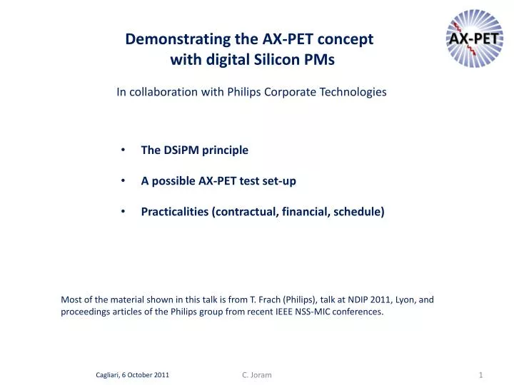
Demonstrating the AX-PET concept with digital Silicon PMs. In collaboration with Philips Corporate Technologies. The DSiPM principle A possible AX-PET test set-up Practicalities (contractual, financial, schedule) .

E N D
Demonstrating the AX-PET concept with digital Silicon PMs In collaboration with Philips Corporate Technologies • The DSiPM principle • A possible AX-PET test set-up • Practicalities (contractual, financial, schedule) Most of the material shown in this talk is from T. Frach (Philips), talk at NDIP 2011, Lyon, and proceedings articles of the Philips group from recent IEEE NSS-MIC conferences. C. Joram Cagliari, 6 October 2011
Different from analogSiPMs: Upon the detection of a photon, the avalanche is actively quenched using a dedicated transistor, and a different transistor is used to quickly recharge the diode back to its sensitive state. C. Joram
Each cell provides a fast asynchronous trigger signal and a slower synchronous data output signal. TDC measurement range : 0 - 163835 ns. C. Joram
a 4-pixel chip Philips terminology: 1 single cell = SPAD (30 x 50 mm2) • 1 pixel • 1 chip C. Joram
Currently the largest device ... and of main interest for AX-PET DLS 6400-88 Test card (not part of kit) backside the 4x4 chips are mounted on a PCB. Every chip has 2x2 = 4 pixels. all pixels are individually readable, but there are only 16 trigger logics. C. Joram
Quite well adapted for readout of crystals (1000 detected photons). No sizable saturation to be expected. C. Joram
trigger S < 1 ms Expect readout rate up to O(1 MHz) C. Joram
Pixel is subdivided in 4 sub-pixels (with 1600 cells each) Depending on the combinations of And/Or, the trigger level of a pixel can be 1, ≥ 2, ≥ 3, ≥ 4 photons Except for the first photon trigger level, any diode breakdown is assumed to be a dark count and is automatically reset if it does not lead to a trigger within 10 to 15 ns from its occurrence. This embedded refresh logic prevents dark counts from accumulating and, eventually, reaching the trigger threshold. System can also be triggered externally. Details to be clarified! C. Joram
Triggering on coincidences of sub-pixels is a statistical process ! The 2nd photon can also come from the same sub-pixel as the 1st no coincidence ! The total trigger generation probability for the number of detected photons as a function of the selected trigger level. The trigger generation probability for the n-th photon as a function of the selected trigger level. If you have 2 photons, the probability that they come from the same sub-pixel is ¼. The ≥2 photon trigger probability is therefore 1 - ¾ = 75%. Watch out for AX-PET WLS signals. The WLS cross-section is small compared to the pixel size. We may not touch all sub-pixels. The signal amplitude can be small (~10 ph). C. Joram
T. Frach, 2009 IEEE Nuclear Science Symposium Conference Record The validation logic A second, higher-level energy-like threshold is implemented in a similar way to distinguish valid events from dark counts. The pixel is subdivided into 64 mutually exclusive regions to allow the adjustment of the validation threshold to up to the minimum of 64 photons. The validation signal is tested at a user-defined time after the trigger has been detected and a fast pixel reset is issued in case of a dark count event to minimize sensor dead time. C. Joram
T. Frach, 2009 IEEE Nuclear Science Symposium Conference Record Collection and Readout If the validation threshold is reached, the state machine changes to the state COLLECT. The collection time is user-defined between 5 and 2560 ns. The photons impinging on the sensor are detected and stored in the cells for later readout. After the expiration of the COLLECT timer, the pixel state machine goes to the state READOUT. Each line of the sensor is selected separately and the number of photons detected in the line is added to the photon accumulator. While reading out one line, the preceding line is recharged to avoid large current surges during the global reset of the pixel. Finally, the pixel controller goes to the RESET state for global pixel recharge and TDC reset, and then back to the READY state. C. Joram
DLD8K (783 mm2 pixel size) C. Joram
(2954 mm2 pixel size) • My interpretations ... • Expect ~280 cps per SPAD for the DLS 6400-22-44 chip (cell size 1500 mm2). • Deadtime per cell: 280 Hz · >20 ns = 5.6 ms / s negligible • Deadtime per pixel: 280 Hz · 6400 · 20 ns = 36 ms / s ~ 4% still small. • Dark count rate per sub-pixel: 280 Hz · 1600 = 450 kHz • Dark count rate per pixel at 4 photon level: (450 kHz)4 · (10 ns)3 = 0.04 Hz C. Joram
Summary (part 1) and some conclusions • Digital SiPM has a number of attractive features which makes it interesting for a concept like AX-PET • The digital approach is ‘in principle’ simpler than the analog one. It avoids the conversion of number of fired cells to charge. • No need of analog readout electronics • High intrinsic time precision • Lower sensitivity to bias voltage and temperature variations • However, the DSiPM requires a dedicated readout. One has, at least initially, to use the readout which Philips provides. Is this a serious limitation? • The performance in terms of sE and stdemonstrated with LYSO crystals are comparable to analog systems. • Nota bene: The current DSiPM approach leads to an asynchronous PET device operated in time-stamped list mode. One records only single hits. Selection of energy (e.g. 511 keV in a crystal matrix) and coincidences must be made at a later stage (for the time being offline). For a full system, the data rates become large and it will require a more detailed study if/how they can be handled. C. Joram
A test set-up is proposed • To demonstrate the AX-PET basic features with digital readout • Energy resolution with long LYSO crystals (3x3x100 or 3x3x150) • Axial resolution from WLS strip arrays • In addition: time resolution in view of TOF-PET capability • This test set-up will be completely independent of the available AX-PET set-up. These quadrants correspond only to a fourth of the DSiPM surface 4 LYSO Crystals (3x3 mm2) 2 WLS strips (0.9 mm) Sketch by Philips ACAD drawing C. Joram
Crystals fit well on pixels, allowing for am active edge of ≥ 0.1 mm around. C. Joram
Configuration for standard AX-PET measurements Set-up to measure time resolution. Use mean time between two DSiPMs or correct time by axial position. Tagged Na-22 source Tagged Na-22 source <T> = 0.5·(T1 + T2) C. Joram
Optional: coincidence set-ups C. Joram
Practicalities • DSiPM have a very thin entrance window (100 mm glass). In the interest of reusing the DSiPM, avoid glue. Use optical grease instead. • Thomas will propose some mechanics which holds all components in place without glue. Set-up will then be operated in a dark box. • An offer has been requested from Saint Gobain for • 5 LYSO crystals 3 x 3 x 100 • 5 LYSO crystals 3 x 3 x 150 • Philips offers an evaluation kit, consisting of • 3 (or 4) sensor arrays DLS 6400-88 • FPGA based readout unit, capable of handling up to 4 sensor arrays • Power supplies • Laptop • Installation, training and user support • The user buys the right to evaluate the kit. In principle the kit has to be given back to Philips at the end of a 3-years evaluation period. C. Joram
The kit is not cheap (~ ). Discussions were held with potentially interested groups. • The kit will probably be shared by 4 partners: ETH-Z, CERN-PH/DT, CERN-ATLAS, Tampere (not yet confirmed). • ETH-Z and CERN-PH/DT will build the presented set-up and evaluate its performance (until summer 2012) • Tampere is interested in building a prototype of a small special PET scanner (until end of 2012) • CERN-ATLAS is interested in the readout of scintillating fibres (2013) Philips indicated a 25% discount on the normal prize as in-kind contribution to the project. If demonstration is successful, further steps could lead to the development by Philips of a scalable/integratable PET module based on the Axial Concept. C. Joram