Download
1 / 14
160 likes | 383 Views
Airport Capacity Analysis . Date: 2013-11. Authors:. This presentation looks at the Airport Terminal Use Case. Background. 1b Airport/train stations - public access and cellular offload. Traffic Conditions

E N D
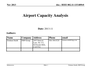
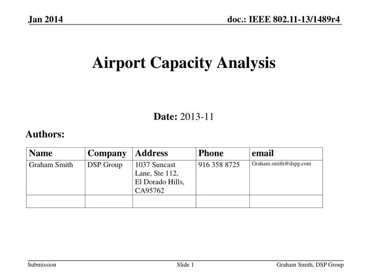
Airport Capacity Analysis Date: 2013-11 Authors: Graham Smith, DSP Group
This presentation looks at the Airport Terminal Use Case. Background Graham Smith, DSP Group
1b Airport/train stations - public access and cellular offload Traffic Conditions Interference between APs belonging to the same managed ESS due to very high density deployment. Interference between APs belonging to different managed ESS due to the presence of multiple operators. Interference with unmanaged networks (P2P) Interference with cellular (e.g. TD-LTE) in in-device coexistence scenario (e.g. User equipments running Wi-Fi and TD-LTE at the same time.) Use Case Travelers are using the network to surf websites, watch movies, play online games and access cloud services. Pre-Conditions High density users access internet through multiple operators’ WLAN network. The venue owner possibly manages or controls multiple operators’ WLAN networks uniformly for the purpose of users’ QoS. Environment The environment is very complex and may suffer severe interference. Each AP serves 120 devices in a 200m2 area. The inter-AP distance is in the range of 15~20m. Single/multiple operators. Applications Video based applications: TV, VOD, Video conference; VHD highly compressed (100 Mbps): 50% of users VPN applications (20 Mbps): 10% of users Game online; 100 Mbps, < 100 ms jitter; < 100 ms latency: 10% of users Internet access: email, twitter, web surf, IM. (20 Mbps): 30% of users Laurent Cariou (Orange) Graham Smith, DSP Group
Channels Ref:Wikipedia Graham Smith, DSP Group
Denver Airport Terminal B Graham Smith, DSP Group
How many people at the gates? Airbus 380 seats 580 in 3 classes (can seat 853 in one class) Graham Smith, DSP Group
Number of Gates = 40,Ave Passengers per Gate = 200 • Percentage gates in use, number using Wi-Fi? • Assume peak = 60%, • Total = 4800 passengers using Wi-Fi in Terminal • Assume 60% waiting at Gates, 40% in eating areas Numbers USERS Graham Smith, DSP Group
Revised figures* for “Use Case 1b”, 120 users per AP • 50% using 15Mbps (VHD) = 15*60 = 900Mbps • 10% using 10Mbps (VPN) = 10*12 = 120Mbps • 10% using 10Mbps (Gaming) = 10*12 = 120Mbps • 30% using 10Mbps (Internet)= 10*36 = 360Mbps • Total traffic for 120 users = 1500Mbps (12.5Mbps per user) • For 4800 users about 40 APs required (42 in example below) Capacity Requirement APs * As suggested by Philip Barber during Telecon presentation Graham Smith, DSP Group
Requirement is 1500Mbps per AP • 1.2Gbps Downlink • 300Mbps Uplink • PHY Rates at 40MHz (10 Channels) • Downlink 8SS, 40MHz, 256 QAM 5/6, Short GI = 1617MbpsThroughput ~1.36Gbps DL only (520k/8k aggregation, 2.285ms pkts) • Uplink 2SS, 40MHz, 256 QAM 5/6, Short GI = 404Mbps PHYThroughput ~357Mbps UL only (260k aggregation, 4.696ms pkts) • Aside: Throughput restricted by max length (5.464ms) and default TXOP Limit (4.090ms). TXOP Limit could be raised. What is the composite traffic result? ~790Mbps DL and ~125Mbps UL • With EDCA overhead, expect ~560Mbps DL and ~90Mbps UL per AP What is Practical PHY Rate and Throughput? Graham Smith, DSP Group
Can’t meet demand if 120 users per AP with current 11ac, need to reduce Users per AP. • DL, 560Mbps capacity, 10Mbps per user = 56 users/AP • UL, 90Mbps capacity 2.5Mbps per User = 36 users/APNote: This assumes a STA is only 2SS capable • Need to see if 36 users per AP is practical. • Alternative would be to assume STA has higher >2SS What Do These Results Tell Us? Graham Smith, DSP Group
40 MHz BW 256 QAM 5/6 (10 Channels) • Typical RX sensitivity is -65dBm • Allow 5dB margin, use -60dBm • TX power 18dBm • Assume +2dBi at AP, -2dBi at STA antennas • Range 40m Free Space (LOS), 23m indoor model (no obstruction) • APs mounted high would tend to LOS but with obstruction losses (e.g. people), say10dB, the LOS is reduced to 13m. Assume 23m range of AP for now RF Considerations Graham Smith, DSP Group
AP Layout APs spaced at 23m allow for a 10 channel scheme. This provides 14 APs covering area for 576 users i.e. 41 users per AP Use of directional antennas would allow closer spacing of APs. Conclusion is that it is possible using 11ac Graham Smith, DSP Group
Need to check if the numbers and distribution of users is valid. Need to check if the traffic (12.5Mbps per User) is valid BUT - on the face of it, (if the 120 users per AP is changed) • 11ac APs at 40MHz BW could (in theory) provide enough capacity and coverage to meet this particular case example. (Antenna directivity would certainly make it possible, but is in ballpark anyhow) What’s missing? • Need for fast handoff between APs for Mobile Users • APs handle distribution of STAs efficiently Points Graham Smith, DSP Group
Could argue that 8SS MU-MIMO is tough in practice but this was the ‘new’ technology invented for 11ac. • Channel re-use can be easily achieved using directional antennas on APs. This would allow even closer locations than the 23m used in example. • This may allow use of 256 QAM 3/4 rather than 5/6. • To work requires • STAs to association to the ‘best’ AP • STAs to handoff to APs when mobile. • Need to analyze each Use Case to find the “Gap” Conclusions Graham Smith, DSP Group