Download
1 / 43
430 likes | 536 Views
Transmission Availability Data System (TADS) TADS Workshops: January 16, 2008 and February 6, 2008 - UPDATED. Workshop Session 2: Forms. TADS Forms Overview. Administrative Forms with Transmission Owner Information 1.1 Non-Reporting Transmission Owner Statement

E N D
Transmission AvailabilityData System (TADS)TADS Workshops: January 16, 2008 and February 6, 2008 - UPDATED Workshop Session 2: Forms
TADS Forms Overview • Administrative Forms with Transmission Owner Information • 1.1Non-Reporting Transmission Owner Statement • 1.2Reporting Transmission Owner Information • Forms for Ties & Jointly-Owned Facilities • 2.1Tie Lines and Jointly-Owned AC and DC Circuits • 2.2Jointly-Owned AC/DC Back-to-Back Converters • Forms for Element Inventory and Summary Outage Data • 3.1AC and DC Circuit Inventory Data • 3.2Transformer Inventory Data • 3.3AC/DC Back-to-Back Converter Inventory Data • 3.4Summary Automatic Outage Data • Forms for Detailed Element Automatic Outage Data • 4.1AC Circuit Detailed Automatic Outage Data • 4.2DC Circuit Detailed Automatic Outage Data • 4.3Transformer Detailed Automatic Outage Data • 4.4AC/DC Back-to-Back Converter Detailed Automatic Outage Data • Form for Event ID Code Data • 5 Event ID Code and Event Type No. Data
Form 1.1 Non-Reporting TO Information (cont’d) • If a non-reporting TO adds TADS facilities during the reporting year, it is required to report on those facilities in that year.
Form 1.2 Problems Encountered • We added pseudo NERC IDs for three TOs for TADS only • PSD00001: Southern Company Transmission (in SERC) to be used instead of their five registered NERC IDs NERC IDCompany Name NCR01166 Alabama Power Company NCR01247 Georgia Power Company NCR01252 Gulf Power Company NCR01273 Mississippi Power Company NCR01322 Southern Power Company • PSD00002: AltaLink Management Ltd. – An unregistered Canadian TO in WECC who will voluntarily report • PSD00003: ATCO Electric – An unregistered Canadian TO in WECC who will voluntarily report • PSD00004: ITC Midwest LLC – purchased the transmission of Alliant West. They have applied for NERC registration. • ITC Midwest LLC is registered with NERC ID NCR10192
Form 1.2 Reporting TO Information (continued) • The forms status table accounts for all forms for reporting TOs
Form 2.1 Tie Lines and Jointly-Owned Circuits • Form 2.1 is reported at the start of each reporting year and at the end of each reporting year. • 2008 will have three submissions of Form 2.1 because of the first quarter reporting requirement • The TO that reports outages for joint-owned circuits also reports the entire circuit length in its inventory • Each DC pole (plus or minus polarity) is a separate DC Circuit • In an AC Circuit, • Transformers are not part of the circuit • In-line switches located inside an AC Substation are part of the AC Circuit Will expand to allow for 3-terminal circuits
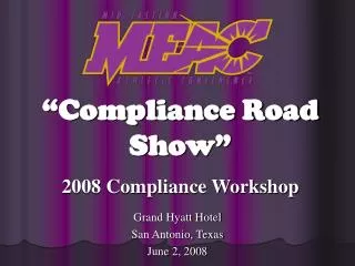
AC Circuit Transformer Exclusion Dashed lines are substation boundaries AC Circuit boundaries are defined by the red “arcs” (A, B, & C) Transformer boundaries are defined by the breaker or disconnect switch
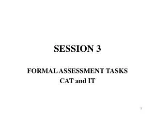
50 mi. 50 mi. 20 mi. 50 mi. 50 mi. Zero mi. Sectionalizing Switches • They are considered “in-line switches,” regardless of location In-line switches are now inside AC Substation C. AC Circuit boundaries (A, B, & C) are the same, but Circuit Miles are different (120 vs. 100).
Form 2.1 Problems Encountered • Some TOs that jointly-own a circuit are not on the NERC Compliance Registry • Example: A customer owns a 345 kV tap off of a registered TOs circuit, but the customer is not a registered TO. If the customer was registered, this would be a jointly-owned 3-terminal circuit. • The registered TO then has reporting responsibility • TO registration of customers and IPPs is before the FERC • Why report tie lines if they are not jointly owned? • Originally thought to be useful for RE review • See the Manual, Section 2.1: “Tie lines for TADS purposes are those AC Circuits (or DC Circuits) that are Elements which connect the AC Substations (or AC/DC Terminals) of two Transmission Owners on the NERC Compliance Registry.” • We will probably drop tie line reporting in the future and just require jointly-owned circuits to be reported
Form 2.2 Jointly-Owned AC/DC BTB Converters • Its similar to Form 2.1, but only requires the reporting of jointly-owned AC/DC BTB Converters
Form 3.1 AC & DC Circuit Inventory Data • In Rows 1-18, the no. of circuits and associated Circuit Miles are adjusted for time in-service of added or retired circuits to properly account for exposure • If circuits are added or retired, this data cannot be filed out until the end of the reporting period • Appendix 7 has examples that calculate the “equivalent” data for no. of circuits and Circuit Miles
Form 3.1 AC & DC Circuit Inventory Data (cont’d) • In Rows 19-25 request AC Multi-Circuit Structure Miles data only • We did not define a “circuit” for common structures, so the no. of circuits is not required • Reminders • Multi-circuit structures that are occupied by only one circuit do not contribute to the tabulation of Multi-Circuit Structure Miles. Examples: • A structure designed to have two 345 kV circuits that has only one circuit on the structure does not contribute • A structure contains a 230 kV circuit and a 138 kV circuit does not contribute since the 138 kV circuit is < 200 kV
Form 3.1 AC & DC Circuit Inventory Data (cont’d) • For common structures that carry circuits owned by different TOs, we expect the TOs to coordinate with each other on their reporting of Multi-Circuit Structure Miles so that no double counting takes place. • As an example, suppose two circuits owned by different TOs occupy common structures for 10 miles. For this section, the combined number of Multi-Circuit Structure Miles reported by the TOs should not exceed 10. We do not want each TO to report 10 miles since that would double count the miles for the region.
Forms 3.2 and 3.3 • Form 3.2 (Transformer Inventory Data) and Form 3.3 (AC/DC Back-to Back Converter Inventory Data) are similar to Form 3.1 for the number of circuits • For Transformers • The Voltage Class is the high-side voltage • Do not include spares… only include transformers that are “in-service” energized and fully connected and that have been declared commercially in service by the TO.
Form 3.4 • Contains Automatic Outage summary data • Columns B and C are self-checks based upon data reported in Forms 4.1, 4.2, 4.3, and 4.4 • They may be eliminated in a future TADS update. • Column D is a number that the TO must derive. Its based upon the number of Elements (AC Circuits, Transformers, etc.) that are “in-service” at the end of the reporting period and which are included in column B on Form 3.1 (AC & DC Circuits), Form 3.2 (Transformers) and 3.2 (AC/DC BTB Converters)
Forms 4.1 - 4.4: Individual Element Outage Data Data that will be recorded for each outage includes… • Several Element descriptors. • The type of Element. A different Form is used for each Element. • Its location: (e.g., Substation Names that define an AC Circuit or Substation Name where Transformer is located) • The Element’s Voltage Class • The TO’s Element Identifier (optional) • For AC or DC Circuits, was it an Overhead or Underground Circuit? • An Outage ID Code • Unique ID assigned by the TO to each specific Element outage being reported • An Event ID Code. • Data for each Event ID Code is described on slides 31-36
Fault Type • Several selections are available (Updated): • No fault • Phase-to-phase fault (P-P) • Single phase-to-ground fault (P-G) • Phase-to-phase-to ground (P-P-G), 3P, or 3P-G fault • Unknown fault type • Fault Types may be determined from recorded relay targets or by other analysis. TOs should use the best available data to determine (1) whether a fault occurred and, if so, (2) what type of fault occurred • Relay targets should be examined as soon as possible after a fault and re-set to prepare for the next fault
Fault Type (cont’d) • If a single fault results in several Element outages, the Element’s protective relays that indicated the Fault Type should be indicated on that Element’s outage. • Element’s whose relays did not indicate a fault should be reported as “no fault occurred” • Example: A 500 kV AC Circuit has a single line-to-ground fault that results in the outage of a 500/230 kV Transformer. The AC Circuit outage would have “ground target” selected as the Fault Type, while the Transformer would have “no fault” selected.
Outage Initiation Code • An Outage Initiation Code that describe where an Automatic Outage was initiated on the power system. Five Outage Initiation Codes are available: • Element-Initiated • Other Element-Initiated • AC Substation-Initiated • AC/DC Terminal-Initiated • Other-Facility Initiated - any facilities not includable in any other Outage Initiation Code • Note: The Protection System is not part of an AC Substation or an AC/DC Terminal. While almost all outages involve the operation of the Protection System, the Protection System is only considered in these codes if the Protection System misoperates and therefore initiates an outage. In this case, it will be classified as Other-Facility Initiated.
Cause Codes • Sustained Outages require two Cause Codes*: • An Initiating Cause Code that describes the initiating cause of the outage. • A Sustained Cause Code that describes the cause that contributed to the longest duration of the outage. (Momentary Outages omit this second code) Example:A lightning strike on an AC Circuit (the Initiating Cause Code is Lightning) that should have cleared normally became a Sustained Outage because of a relay misoperation (the Sustained Cause Code could be Failed Protection System Equipment or Human Error) • Seventeen (17) Cause Codes are defined • For 2008 an additional code is also allowed (“Unavailable”) *See 2008 exceptions in the Manual, p.13, column N, and discussed next.
Cause Codes – 2008 Exceptions • All Momentary Outages must supply this code, and the “Unavailable” Cause Code cannot be used for Momentary Outages. Sustained Outages may use the “Unavailable” code in 2008 only for either the Initiating Cause Code or the Sustained Cause Code, but not both. If the TO has the ability to capture Initiating and Sustained Cause Codes, the “Unavailable” code is not to be used.
Weather (excl. lightning) Lightning Environmental Contamination Foreign interference Fire Vandalism, terrorism, malicious acts Failed AC Substation equipment Failed AC/DC Terminal equipment Failed Protection System equipment Failed AC Circuit equipment Failed DC Circuit equipment Vegetation Power system condition Human error Unknown Other Unavailable Listing of Cause Codes Definitions of each cause code are included in the Manual, Appendix 6
Vegetation Cause Code and FAC-003-1 • It is possible for more Vegetation Cause Codes to be recorded for outages than are reported as vegetation outages under FAC-003-1 (Vegetation Management Program Standard) • TADS records Momentary Outages due to vegetation while FAC-003-1 does not • The TADS definition of a Sustained Outage is different that the Sustained Outage definition in FAC-003-1. Under FAC-003-1, a Sustained Outage is “The deenergized condition of a transmission line resulting from a fault or disturbance following an unsuccessful automatic reclosing sequence and/or unsuccessful manual reclosing procedure.” • For a circuit with no automatic reclosing, a vegetation outage would not be “counted” under FAC-003-1 if the TO has a successful manual reclosing
Outage Mode Code • The Outage Mode Code describes whether an Automatic Outage is related to other Automatic Outages. Several Outage Mode Codes are provided: • A Single Mode Outage is an Automatic Outage which occurred independent of any other outages (if any). • A Dependent Mode Initiating Outage is a Single Mode Outage that initiates one or more subsequent Automatic Outages. • A Dependent Mode Outage is one that occurred as a result of an initiating outage, whether the initiating outage was an Element outage or a non-Element outage. • A Common Mode Outage is one of two or more Automatic Outages with the same Initiating Cause Code and where the outages are not consequences of each other and occur nearly simultaneously (i.e., within cycles or seconds of one another). • A Common Mode Outage Initiating Outage is a Common Mode Outage that initiates one or more subsequent Automatic Outages.
Outage Example #1 • A tornado takes down a tower that is a common structure for two 230 kV circuits • How many outages are reported? • The Fault Type was for one circuit was determined to be “ground target,” while the Fault Type for the second circuit was “phase target.” • What was the Outage Initiation Code? • What was the Initiating Cause Code and the Sustained Cause Code? • What was the Outage Mode Code?
Outage Example #2 • A circuit breaker opens due to low gas pressure, resulting in the outage of a 500 kV circuit • How many outages are reported? • What is the Fault Type? • What was the Outage Initiation Code? • What was the Initiating Cause Code and the Sustained Cause Code? • What was the Outage Mode Code?
Outage Example #3 • Insulator contamination causes a fault on a 230 kV AC Circuit, but a breaker on one end fails to open due to a failure of a relay to operate properly. A second 230 kV AC Circuit, which is connected to the same bus as unopened breaker, is outaged as a result of the first circuit’s breaker failing to open. The failed relay was manually isolated, and both lines were returned to service with no other repairs. • How many outages are reported? • The Fault Type was determined to be “ground target” for the first circuit, and second circuit did not experience a fault, it’s Fault Type was “no fault.” • What was the Outage Initiation Code? • What was the Initiating Cause Code and the Sustained Cause Code? • What was the Outage Mode Code?
Outage Example #4 • A 345/138 kV Transformer in one leg of a three-terminal 345 kV AC Circuit is outaged due to a 138 kV bus fault caused by contact with a snake. The Transformer and its terminal are isolated, but the other terminals remain in service. • How many outages are reported? • What is the Fault Type? • What was the Outage Initiation Code? • What was the Initiating Cause Code and the Sustained Cause Code? • What was the Outage Mode Code?
Outage Times • The Outage Start Time - The date (mm/dd/yyyy) and time (hhhh:mm), rounded to the minute, that the Automatic Outage of an Element started • Outage Start Time is expressed in Coordinated Universal Time (UTC), not local time • Common time reference will allow REs and NERC to assign common Event ID Codes to Events that cross TO and RE boundaries • The Outage Duration (for Sustained Outages only), rounded to the nearest minute. • Momentary Outages are recorded as a zero minute outage duration time to avoid confusion in rounding to the nearest minute • For outages that continue beyond the reporting period, see Section 4.1 of the Manual
Partial Outages • With one exception, TADS does not recognize partial power flow outages. • The exception is a three-terminal circuit with a Transformer on one leg. • If terminal A or B open, an AC Circuit outage is recorded. • The AC Circuit is considered to be restored when partial power flow is restored on both A & B and the Transformer (TADS or non-TADS) is out-of-service.
Form 5: Event ID Code Data • An Event ID Code. • An Event is a transmission network incident that results in the Sustained or Momentary outage of one or more Elements. • Each TO will assign its own Event ID Code, with the reporting year appended to it. Regional Entities and NERC will assign common Event ID Codes if outages affect two or more TOs.
Form 5: Event ID Code Data (cont’d) • An Event associated with a Single Mode Automatic Outage will have just one Event ID Code. • Each outage in a related set of two or more outages (e.g., Dependent Mode, Dependent Mode Initiating, Common Mode, or Common Mode Initiating) shall be given the same Event ID Code.
Form 5: Event ID Code Data (cont’d) • The Event Type Number • Event Type Number Possibilities
Event Type No. 30 or 40 • To qualify for an Event Type No. 30 or 40, the outages must be a direct result of the circuits occupying common structures. These characteristics will generally apply. • The Outage Initiation Codes are either Element-Initiated or Other-Element Initiated. • The Outage Mode Codes are one of the following: (a) Dependent Mode Initiating (one outage) and Dependent Mode (second outage); (b) Common Mode Initiating and Common Mode (two outages); or (c) both Common Mode (two outages)
Assign an Event Type No. • On one circuit, a conductor breaks (outaging the circuit), and the conductor swings into a second circuit on common structures and outages the second circuit. Both circuits have Normal Clearing. Event Type No. = ? • Two AC Circuits on common structures are outaged due to a bus fault in the AC Substation were the circuits terminate. Both circuits have Normal Clearing. Event Type No. = ?
Form 5: Event ID Code Data (cont’d) • Was the Event was associated with the filing of a disturbance report (an EOP-004-01 disturbance report filing)? • TO may select “yes, “no,” or “unknown” • NERC staff will examine reports to fill in “unknown” responses • Year-to-date public (i.e., non-confidential) data of all disturbance report filings are located at http://www.nerc.com/~filez/dawg-disturbancereports.html • Info on disturbance reports is an “impact measure” • Since TADS tracks a part of the transmission system, other potential measures (load lost, transmission service interrupted) would be a subset of the impacts
AC Multi-Owner Common Structure Flag • For AC Circuits only: AC Multi-Owner Common Structure Flag = 0 Not applicable. The circuit is not on common structures with another circuit, or the circuit is on common structures, but all circuits are owned reported by the same Transmission Owner. No analysis of the Event ID Code or the Event Type Number is required by the Regional Entity. = 1 Circuit is on common structures with another circuit that is being reported and owned by a different TOs Transmission Owner. The Regional Entity will need to examine Outage Start Times with this same flag to determine whether a second circuit had an outage with nearly the same Outage Start Time, and if so, whether the TOs properly coordinated their Event ID Codes and Event Type Numbers.
Examples: Inventory & Outage Mode • Examples in the Manual were developed to assist TOs in responding properly to TADS data request • Both inventory and outage mode examples are included in the data instruction manual • Inventory examples are designed to demonstrate proper calculation of entries in Form 3.1 (AC/DC Circuit Inventory Data) • But they are applicable to all Elements • Outage mode examples are provided to illustrate several AC Circuit & Transformer outage scenarios
TADS Metrics • Intent of the proposed metrics is to assist in measuring performance • Given richness of the data collected, metrics can be computed for many data combinations • Comprehensive set of metrics not established yet – waiting until sufficient amount of data collected • Basic metrics presented here will be reported to describe the performance of each Element for the reporting year.
Metrics and Data Analysis - Basic Metrics • Outage frequency (Sustained, Momentary, and total) • For AC and DC Circuits: • Outage frequency/100 Circuit Miles (Sustained, Momentary, and total). Additional calculations for Events 30 and 40 per 100 Multi-Circuit Structure Miles • Additional calculations will exclude outages not related to mileage • For Sustained Outages: • Outage Duration • Mean Time Between Failure -MTBF • Mean Time to Repair – MTTR • Median Time to Repair - MdTTR • Percent Availability • Percent of Elements w. zero outages. • Percent of Element outages that were associated with a disturbance report.
Metrics and Data Analysis- Additional Items • MTBF and Percent Unavailability will not follow standard industry terms since no planned outage data will be collected in Phase I • Lots of ways to “slice” metrics (Cause Code, Outage Mode, Event Type#, etc.) • Additional metrics will be determined – we will work with the data looking for meaningful information


![AIP-2 Kickoff Workshop [Your Topic] Session Overview](https://cdn3.slideserve.com/6539919/aip-2-kickoff-workshop-your-topic-session-overview-dt.jpg)