Download
1 / 57
580 likes | 699 Views
Muon Beamline and Detectors Tracker Calorimeter Cosmic Ray Veto. George Ginther 14 February 2013. Introduction (adapted from material generated by S. Feher ).

E N D
Muon Beamline and DetectorsTrackerCalorimeterCosmic Ray Veto George Ginther 14 February 2013
Introduction(adapted from material generated by S. Feher) • The goal of the Muon Beamline is to facilitate selection and transport an intense beam of low momentum negative muons (~1018 stopped muons during three years of operation of the experiment) to a target, located in the Detector Solenoid, where many of those muons stop • The majority of the stopped muons will be captured by the target nuclei, and many others will decay in orbit into electrons and neutrinos • The intent is to search for evidence of the conversion of stopped muons into electrons • The tracker detects the electrons and suppresses backgrounds through high resolution reconstruction of the electron’s track • The calorimeter and cosmic ray veto detectors provide additional information to identify and suppress backgrounds to confirm the signal (should it occur)
Components • Vacuum enclosures • and associated seals, feedthroughsand vacuum pumps • blanks for pump down tests • Collimators • Muon stopping target • Tracker • Calorimeter • Muon beam stop • Detector support • And support for installation and detector maintenance • Stopping target monitor • Shielding around the TS and DS • Cosmic ray veto detectors • …and associated readout, instrumentation and infrastructure
Muon Beamline Requirements(adapted from materials generated by S. Feher) • Support and align the detectors • Install the detectors • Maintain vacuum in the Production Solenoid (PS), Transport Solenoid (TS) and Detector Solenoid (DS) vacuum space • Prevent migration of radioactive molecules from PS to the detector region • Charge and momentum select particles, preferentially muons, from the particle beam spiraling downstream from the PS to DS • Reduce the heat load to the TS superconducting coils • Protect the detectors from neutron and proton background • Capture muons in the stopping target • Stop the rest of the muons that were not captured inthe stopping target and reduce the background in the detectors generated by the secondary protons and neutrons • Monitor the number of captured muons at the stopping target
Detector Requirements(Summarized from materials generated by A. Mukherjee, S. Miscetti and C. Dukes) • Tracker must have superior position resolution • Minimize material in path of muons • Tracker and calorimeter must be able to function in vacuum and not spoil the vacuum due to leaks/outgassing • Cosmic ray veto must have high efficiency to identify cosmic rays that have the potential to generate signal like events • Minimize penetrations through the cosmic ray veto • Detectors must have good time resolution and handle high rates • Detectors must have low mean times between failures and high uptimes • And survive the accumulated radiation doses • Detectors should be serviceable/repairable in a short time when necessary
Tracker • Total of 21600 gas filled straws in 18 stations • 5mm diameter each • 25mm diameter wire in center of straw • Detector is ~3m long • High voltage ~1500V • Argon/CO2 gas • LV power (~20kW) and cooling • High currents (perhaps up to 10kA) • Additional instrumentation for precision monitoring • Magnetic field, temperature and alignment • Clean room for detector during servicing • Local dehumidification (perhaps 5kW) • Chiller and phase separator
Calorimeter • 1936 LYSO crystals arranged in 4 vanes • Each crystal readout with two large area APD’s • Detector is ~ 1.3 m long • High voltage • Laser calibration • Radioactive source calibration • Neutron source bunker
Neutron Absorbers(adapted from materials generated by S. Feher) • Standard concrete blocks? • End Cap Shielding designed to be moved downstream to allow access to the detectors inside the DS.
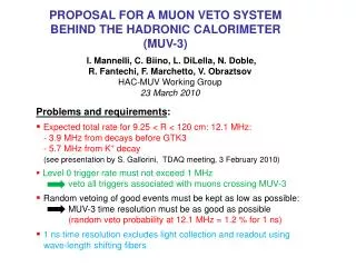
Cosmic Ray Veto • Three layers of extruded scintillator counters with embedded wavelength shifting fibers • Require 2/3 adjacent counters in different layers to define a muon and a ~50 ns veto window • 58 modules, each with 36 counters • 2,088 counters, each with 4 fibers • 16,704 photodetectors: SiPMs • 330 m2
Cosmic Ray Veto Jason Adams, Zach Drumheller
Detector Support Structure S. Feher- DOE CD-1 Review
Infrastructure • Power and cooling for large loads • Emergency power • Climate control (and cleanliness) • Stable base of operation • Support loads/maintain detector alignment • Facilitate operations • Space for signal processing and controls (racks) • Routing of cables and other services---trench • Cryogen and gas distribution • Safety • Radiation (protection and shielding), fire safety, cryogens, Oxygen Deficiency Hazards, magnetic fields, large volume vacuum spaces (confined spaces), high pressure gases, egress paths • Lighting • Access (for receiving, storage and to detector elements) • Materials handling • Crane/house air
Initial Phases of Experiment Operation • Installation • Getting the equipment into place • Locations for pumps, chillers, infrastructure • Routing of services • power distribution • vacuum and cryo lines • signals and controls • Access and clearance for assembly/installation (an ongoing concern) • Staging/storage areas for support equipment/tooling (an ongoing challenge) • Commissioning • Putting the equipment into service • Need to keep detector clean while other activities are underway in parallel • Detectors must be accessible • Operate tracker and calorimeter in service position • Calibration too? • Precision mapping of detector solenoid field • Establishing transmission of muon beam to target
Ongoing Experiment Operations • Operation • Expect to operate around the clock most of the year • Recording data • Calibrations • Select positive muons • Operate detector solenoid at reduced current • Normalization • Anticipate no access to detector level while beam is being delivered • May need to ramp down solenoid to service detector • Anticipate regular need for access (frequency not determined but not likely less than once a month) • Maintenance • Anticipate accessing detectors in DS bore perhaps once a year • Likely a several week operation • Keeping the equipment running at peak efficiency and addressing features observed during operation
Equipment storage during detector opening • External beam stop? • Muon Stopping Target Monitor (and associated supports and infrastructure) • Clean room components • Clean room dehumidifier • Scaffolding or access components (ladders) • Scissors lift (or two)? • Ladders • Detector rail system and supports • Hydraulic pump cart • IFB blank • Tool boxes
Vacuum System Design Five major components (excluding the beam pipe - part of the Solenoid System): • PS Enclosure • DS Enclosure • Vacuum Pump Spool Piece (VPSP) • Instrumentation Feed-through Bulkhead (IFB) • Cryostat Interconnects • External Vacuum System • dry screw pumps, turbo molecular • cryopumps, pipes, valves • Powering, Monitoring and Interlocks • Above 10-3 torrinterlock at the DS activates: • Tracker HV off • Gate valves for the cryo pumps closed • By-pass valves opened • ----accommodate remote handling S. Feher- DOE CD-1 Review
Collimators Col 5 Col 3d Collimators are made of copper ~1000 kg each Col 3u Col 1 COL3 need to be rotatable To select Positive particles as well for calibration purposes S. Feher- DOE CD-1 Review
Muon Beamline Shielding Design External MuonBeamline Shielding Concrete blocks are envisioned to place around the Transport Solenoid region Exact configuration strongly dependson the cryostat support structure S. Feher- DOE CD-1 Review
Stopping Target Design Stopping Target: 17 flat 200 µm thick pure aluminum discs Tungsten support; low volume, alignment might require extra stiffening S. Feher- DOE CD-1 Review
Stopping Target Monitor Stopping Target Monitor is a germanium detector monitoring muonic X-rays from the capture process outside of the vacuum volume S. Feher- DOE CD-1 Review
Proton Absorber The proton absorber made of polyethylene, is a tapered cylindrical shell 0.5 mm thick with a radius slightly smaller than the inner radius of the tracker. S. Feher- DOE CD-1 Review
Muon Beam Stop Approximate weight: 3300Kg S. Feher- DOE CD-1 Review
Tracker Requirements • Geometric • No mass at r<~40cm, • Low mass for ~40<r<85cm • Performance • High-side resolution for 105MeV/c electron: p< 180KeV/c • Acceptance ≥ 20% • Operation • Low leak rate at 10-4Torr ambient • System MTBF > 1 year • Repair time <2 daysfrom time tracker is accessible to time tracker is ready to reinstall • Tolerate 500kHz/cm2 rate A. Mukherjee - CD-1 Review
Tracker Geometric Requirement Target Measure these Blind to these A. Mukherjee - CD-1 Review
Tracker Resolution Requirement Why asymmetric? • An important background is DIOs, below 105MeV/c • Upward smearing brings background into signal region … bad • Downward smearing moves signal into background … not as bad Signal E (MeV) A. Mukherjee - CD-1 Review
Tracker Conceptual Design • 18 “stations” with straws transverse to beam • Naturally moves readout and support to large radii A. Mukherjee - CD-1 Review
Tracker Straw Assemblies • 100 straws, in two staggered layers, form one panel A. Mukherjee - CD-1 Review
Tracker Straw Assemblies • 6 panels → a “plane” • 2 planes → a “station” • 18 stations in Tracker A. Mukherjee - CD-1 Review
Calorimeter Requirements The calorimeter requirements are described in Mu2e-doc-864. • The calorimeter will be used to confirm that a reconstructed track is well-measured and was not created by a spurious combination of hits in the tracker. • Measure the position of the conversion electron σ(x) ≤ O( 1 cm). • Compare the energy deposited in the calorimeter to the reconstructed track momentum σ(E) ≤ O( 2 %). Energy scale small w.r.t. resolution. • Check the time of the energy deposit in the calorimeter to a time determined from the tracker σ(t) O(≤ 1 ns). • Provide particle identification to separate, for example, electrons from muons. • Provide a trigger that can be used for event selection • Keep functionality in a 50 Gy/year radiation environment L.Y loss < 10% S.Miscetti, DOE CD1 review
Calorimeter Baseline Design • 1936 LYSO crystals arranged in 4 vanes ~ 1.3 m long. • Electrons spiral into the transverse, checkerboard face of the array. • APDs and FEE on back side. • 4 vanes represents the best balance between acceptance and crystal volume (cost). Z= Beam axis Vane dimension: 13x33x132 cm3 Crystal+APD length ~ 13 cm S.Miscetti, DOE CD1 review