Download
1 / 12
120 likes | 230 Views
CricketSat LC Receiver. Assembly Manual. Mike Fortney 04/02/2006. Index. Parts List Circuit Board Assembly Testing Troubleshooting. Parts List. Protection diode (1N4001) Audio jack connector Three small yellow 0.1uF capacitors Blue cylindrical 47uF capacitor

E N D
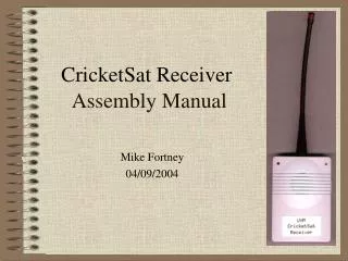
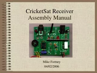
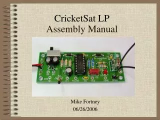
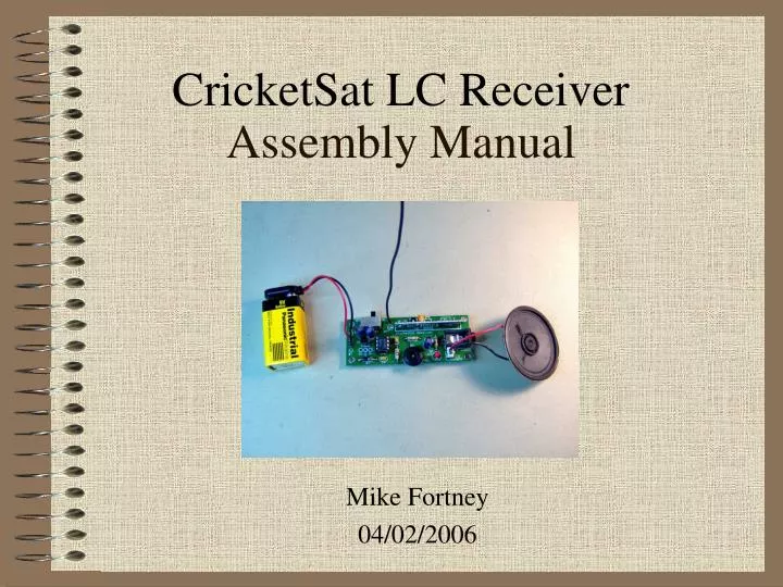
CricketSat LC Receiver Assembly Manual Mike Fortney 04/02/2006
Index • Parts List • Circuit Board Assembly • Testing • Troubleshooting
Parts List • Protection diode (1N4001) • Audio jack connector • Three small yellow 0.1uF capacitors • Blue cylindrical 47uF capacitor • Volume control potentiometer • 10 ohm resistor, brown-black-black-gold • 680 ohm resistor, blue-gray-brown-gold • 180K ohm resistor, brown-gray-yellow-gold • Speaker • 6” black antenna wire • 1” black jumper wire • Green printed circuit board • 9-Volt battery snap connector • Power switch • RF receiver module • LM386 IC chip • 8-pin DIP socket • 5-Volt regulator (black 3-pin device) • Red LED
Circuit Board Assembly (1 of 7) White band • D1, 1N4001 diode (polarized) • R2, 680 Ohm (blue-gray-brown) • R3, 180 kOhm (brown-gray-yellow) • R5, 10 Ohm (brown-black-black) • C3, 0.1 uF capacitor • C4, 0.1 uF capacitor • C5, 0.1 uF capacitor
Circuit Board Assembly (2 of 7) Notch end up Longer lead is positive (+) • Masking tape may help • SW1, switch • 8-pin socket for U3 • R4, volume potentiometer • D2, red LED (polarized) • J1 audio jack • J2 speaker 2-pin header
Circuit Board Assembly (3 of 7) White bands up Flat edge of U1 down Notch end of U3 up White band on C6 to the right • U1, 5-V regulator • U2, RF receiver module • U3, LM386 amplifier • C1, 47 uF capacitor (polarized) • C2, 47 uF capacitor (polarized) • C6, 47 uF capacitor (polarized)
Circuit Board Assembly (4 of 7) Route through strain relief holes Solder wires on top of board Snip off excess wire Red lead to B+ Black lead to B- • 9-Volt battery snap connector (POLARIZED)
Circuit Board Assembly (5 of 7) Solder antenna wire on top of board. Trim excess wire. • Black 6-inch antenna wire
Circuit Board Assembly (6 of 7) Solder wire on top side of circuit board. Trim excess wire. Solder wire to this lead of R3 on this side of circuit board. • Black 1-inch jumper wire
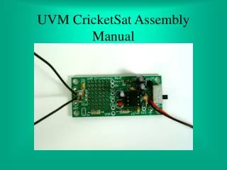
Circuit Board Assembly (7 of 7) • Attach battery • Attach speaker to J2 (non-polarized) • Assembly is complete!
Testing • Slide power switch to “ON” position. • The red LED should light and change brightness with according to signal strength. • If the LED does not light, TURN OFF IMMEDIATELY and proceed to the next slide “Troubleshooting” • Turn the volume control to a mid position and you should hear a hiss from the speaker. • Test the unit with a CricketSat. You should hear a tone or clicking sound up to 1000 feet away.
Troubleshooting • No sound or lights, no smoke • Try a new battery • Insure that slide switch is working properly • Check if battery leads correctly attached to board, red +, black - • Check if D1 diode is properly installed, white band - • Check if amplifier IC and RF receiver modules installed properly • No sound, but lights • Turn volume control to a median setting. Should hear hissing sound • Does not receive CricketSat tone or pulses • Receiver module may be faulty or need re-tuning