Download
1 / 43
440 likes | 705 Views
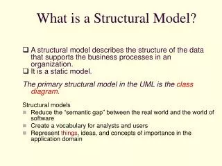
What is a Structural Model?. A structural model describes the structure of the data that supports the business processes in an organization. It is a static model. The primary structural model in the UML is the class diagram . Structural models

E N D
What is a Structural Model? • A structural model describes the structure of the data that supports the business processes in an organization. • It is a static model. The primary structural model in the UML is theclass diagram. Structural models • Reduce the “semantic gap” between the real world and the world of software • Create a vocabulary for analysts and users • Represent things, ideas, and concepts of importance in the application domain
Objects • Any thing can be viewed as an object. • Each object in a system has: state,behavior,identity • The state of an object is one of the possible conditions in which it may exist • The behavior of an object determines how it responds to requests from other objects • The identity of an object means that each object is unique
Class • Each object is an instance of some class • A class is a template for objects • Objects cannot be instances of more than one class • A good class captures one and only one abstraction – it should have one major theme • The name of a class should be a singular noun, that best describes the abstraction
Classes • In the UML, classes are represented as compartmentalized rectangles • The top compartment contains the name • The middle compartment contains the structure (attributes) • The bottom compartment contains the behavior (operations)
Class Diagram • The Class Diagram is a static model that captures both processing requirements and data storage requirements of the system. • The class diagram produced during OO analysis is a logical model. It shows what classes of objects are required without showing how the objects might be implemented or how the user might interact with them.
Documentation The documentation should state the purpose of the class, not the structure. For example, a StudentInformation class could be documented as: Information needed to register and bill students. A student is someone who takes classes at the University. (Not: The name, address, and phone number of a student.)
Entity Classes An entity class • models information and associated behavior that is generally long lived • is typically identified during the analysis phase • is often called a domain class, since it usually deals with an abstractions of a real world entity
Boundary Classes A boundary class • handles communication between the system and the system environment • models the system interface To identify boundary classes, examine the actor/use case scenario pairs.
Control Classes A control class • models sequencing behavior specific to one or more use cases • coordinates the events needed to realize the behavior specified in the use case • “runs” or “executes” the use case • is typically application dependent
Responsibilities and Collaborations • A class embodies • a set of responsibilities that define the behaviorof the objects in the class • a set of attributes that define the structure of the objects in the class • Objects collaborate • they work together to service a request
Representing Behavior and Structure • The responsibilities are carried out by the operations(methods, functions) defined for the class. Each operation should do only one thing. • Objects in a class have a value for every attribute of the class. These values do not have to be unique.
Attributes • Units of information relevant to the description of the class Only attributes important to the task should be included
Operations • Action that instances/objects can take Focus on relevant problem-specific operations (at this point)
Representing Behavior and Structure A common convention for attribute and operation names consisting of multiple words is to write the name without spaces, but capitalize the first letter of each word, except the first word: e.g. memberName, addNewMember. Class names consisting of multiple words are handled similarly, but the first letter of the first word is also capitalized: e.g. StoreClerk.
Relationships • In order for objects to collaborate, there must be an association between these objects. • A special type of association, where one object is a part of another object, is called an aggregation relationship.
Association Relationships • An association relationship between classes represents a link between the objects in those classes. • The number of objects connected depends upon the multiplicity of the association. • In the UML, association relationships are shown as lines connecting the classes.
Association Relationships The numbers and symbols representing multiplicity include a “1” for one and asterisk (*) for many.
Association Relationships • Additional numbers and symbols are often added to indicate optional or mandatory relationships. • Often these are referred to as minimum and maximum multiplicity.
Association RelationshipsRational Rose Example 0..* Tenant rents 1..* 1..* Rental property unitAddress change Owner Name() is for 1 1 0..* 0..* LeaseAgreement
Aggregation Relationship Whole-part relationships are usually called aggregation relationships.
Aggregation Relationships • An aggregation relationship is a specialized form of association in which a whole is related to its parts. • This kind of relationship applies whenever one can say “ … is a part of …”. • In UML notation, an aggregation relationship is an association with a diamond next to the class denoting the aggregate. • The “whole” is called aggregate class. • The “part” is called aggregation class
Aggregation RelationshipsRational Rose Example Tenant 0..* 0..* TenantName 1..* 1..* Rental property 1 1 UnitAddress OwnerName change Owner Name() 1 1 1..* 1..* 0..* 0..* LeaseAgreement BeginningOccupancy Lease Term EndingOccupancy Deposit Term MonthlyRent 0..* 0..* RentDueDate
Composition Relationship • A strong form of aggregation relationship is sometimes called a composition relationship. • In a composition relationship, the parts do not normally exist without the whole.
Naming of Relationships • An association may optionally be named. • The name is typically an active verb or verb phrase that communicates the meaning of the relationship. • Aggregations are not usually named, since the relation is always of the type “… is a part of …” • Choose the verb to be meaningful when read from left to right or top to bottom.
Role Names • The end of an association, where it connects to a class, is called an association role. • Instead of association names, role names may be used. • A role name is a noun that denotes the purpose of the association. Renter of Property Rental property Tenant 0..* 1..* 1..* unitAddress TenantName OwnerName change Owner Name()
Reflexive Relationships • A reflexive association or aggregation is an association or aggregation relationship among objects of the same class. • Role names, rather than association names are typically used for reflexive relationships.
Generalization/ Specialization Hierarchies Exhaustive subclasses cover all possible objects, so the general class, called abstract class, will not have any objects.
Inheritance • A subclassinherits all attributes and operations from one or more superclasses(parent classes). • The relationship is a “is a kind of” relationship: objects in the subclass are special cases of the superclass. • We can have a hierarchy of classes. Classes at the bottom of the hierarchy inherit from all ancestor classes.
Inheritance • Subclasses may have additional attributes and operations, not defined in an ancestor class. • Subclasses may also override attributes and operations defined in an ancestor class with their own versions: this is called polymorphism. Inheritance and polymorphism are major factors for reuse: They allow the creation of objects from augmented or modified classes.
Generalization • Generalizationprovides the capability to create superclasses that encapsulate structure and behavior common to several classes. • Classes are examined for commonality of structure and behavior. • Be on the lookout for synonyms, since attribute and operation names are expressed in natural language.
Specialization • Specializationprovides the ability to create subclasses that represent refinements to the superclass – typically, structure and behavior are added to the subclass, but they may also be modified (polymorphism).
Single Inheritance versus Multiple Inheritance • With single inheritance, a class has one chain of ancestors • e.g. a caris a kind of motor vehicle; a motor vehicleis a kind ofvehicle
Single Inheritance versus Multiple Inheritance • With multiple inheritance, a subclass may have more than one chain of ancestors • e.g. an amphibious vehicleis a kind of road vehicle; a road vehicleis a kind ofvehicle; an amphibious vehicleis a kind ofwater vehicle; a water vehicleis a kind ofvehicle). • Multiple inheritance may lead to conflict.
Inheritance versus Aggregation Inheritance is often misused. For example, Student and Staff can be subclasses of Person. Problems arise if staff can also be students.Using aggregation classes may solve the problem:
Steps for Object Identification and Structural Modeling 1. Identify candidate classes by performing textual analysis on the use-cases. 2. Brainstorm additional candidate classes, attributes, operations, and relationships by using the common object list approach. 3. Role-play each use-case. 4. Create the class diagram. 5. Review the structural model for missing and/or unnecessary classes, attributes, operations, and relationships. 6. Incorporate useful patterns. 7. Review the structural model.
Packages • If the class diagram become large, it will be quite difficult to use for an overview of the system. • In such cases it might be necessary to create a high-level view of the system, using some kind of partitioning or clustering scheme. • Clustering can be done after the initial model is produced to facilitate presentation and further work, or beforehand to allow for division of work between workgroups from the outset. • UML calls these clusters packagesand provides a modeling notation called package diagram.
Package Relationships • If objects in one package communicate with objects in another package, then a dependency relationship exists between the packages. • The dependent package is called the client package, and the other package is called the supplier package. • The relationship is shown in the UML as a dashed arrow, pointing to the supplier package User Interface Persistent Objects